ST215 engine rebuild
Two OH five (Talk | contribs) (Created page with "== ST215 Caldina Engine Rebuild == OK, here's the plan The engine in Black Beauty is tired and suffering big end rattle I want to go aftermarket ECU with coil on plug in Hannib...") |
Two OH five (Talk | contribs) (→ST215 Caldina Engine Rebuild) |
||
| Line 38: | Line 38: | ||
http://i21.photobucket.com/albums/b277/Stevo_st205/Caldina%20Engine%20Rebuild/IMG_1199.jpg | http://i21.photobucket.com/albums/b277/Stevo_st205/Caldina%20Engine%20Rebuild/IMG_1199.jpg | ||
Top mount intercooler. Significantly better than the 185 setup, bigger and thicker. Also equipped with plastic tanks | Top mount intercooler. Significantly better than the 185 setup, bigger and thicker. Also equipped with plastic tanks | ||
| − | + | ||
| + | http://i21.photobucket.com/albums/b277/Stevo_st205/Caldina%20Engine%20Rebuild/IMG_1200.jpg | ||
| + | |||
Front of the engine looks familiar. Note that the cambelt tensioner pulley is different with a 1/2" square drive in the centre for some reason | Front of the engine looks familiar. Note that the cambelt tensioner pulley is different with a 1/2" square drive in the centre for some reason | ||
| Line 67: | Line 69: | ||
Disassembled IAC control block. You can see the barrel "throttle" of the ISC and you can also see that the manifold heater is just a very short direct connection channel. It does not go round the TB in any way | Disassembled IAC control block. You can see the barrel "throttle" of the ISC and you can also see that the manifold heater is just a very short direct connection channel. It does not go round the TB in any way | ||
| − | + | http://i21.photobucket.com/albums/b277/Stevo_st205/Caldina%20Engine%20Rebuild/IMG_1209.jpg | |
4 layer exhaust manifold gasket is made up of 4 single identical steel gaskets | 4 layer exhaust manifold gasket is made up of 4 single identical steel gaskets | ||
Revision as of 11:39, 17 August 2011
ST215 Caldina Engine Rebuild
OK, here's the plan
The engine in Black Beauty is tired and suffering big end rattle
I want to go aftermarket ECU with coil on plug in Hannibal with a sidefeed manifold
The solution is obvious to me
First buy one of these. It's apparently a low mileage ST215 caldina engine

The idea is to refresh this bottom end with new bearings, pumps, pressure relief valves etc etc. It will then go into Black Beauty which will revert to standard ECU running notionally stock power as my reliable daily driver The good bits will then be transferred onto my current forged block
Along the way I'll try to detail a few things and probably bore everyone to photographic death :lol:
An interesting feature. The ST215 uses a turbo that looks similar on the compressor side to a CT20 ST205 turbo. The hotside is obviously a little different! It's an integrated hotside/manifold setup
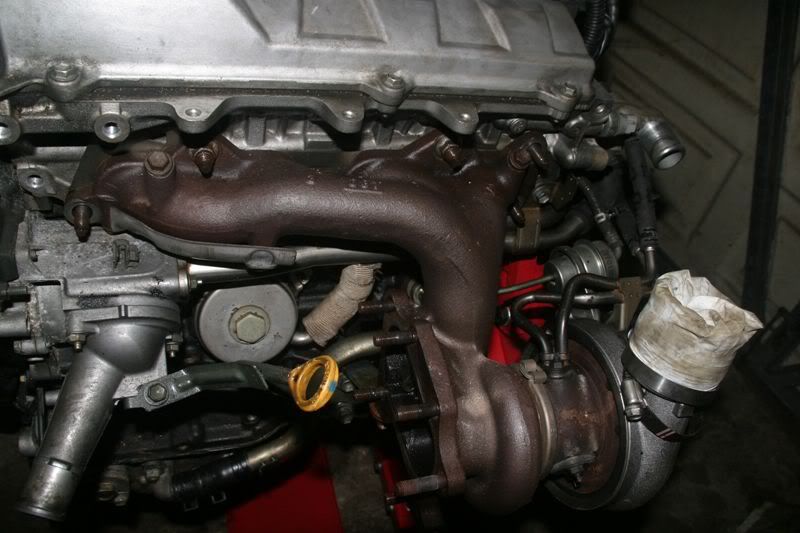
For reference, a 205 WRC manifold plonked on top. You can see that the lineup is about the same as the 205 setup position wise
[img]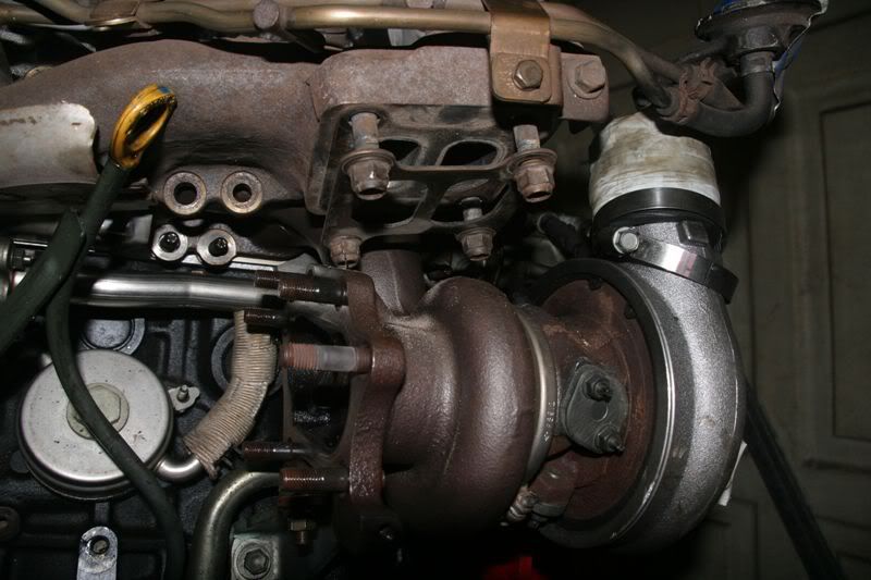 Mmmmmm sidefeed manifold and coil on plug goodness :D :D
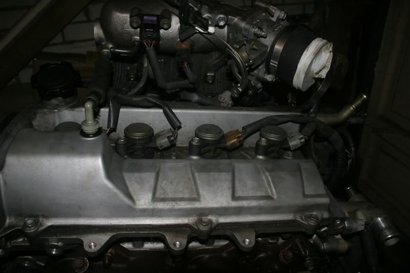 There's two things to note here. There's a distinct lack of even a vestigial dizzy. Ant the water elbow only has one sensor. No more ECU + dash sensor setup
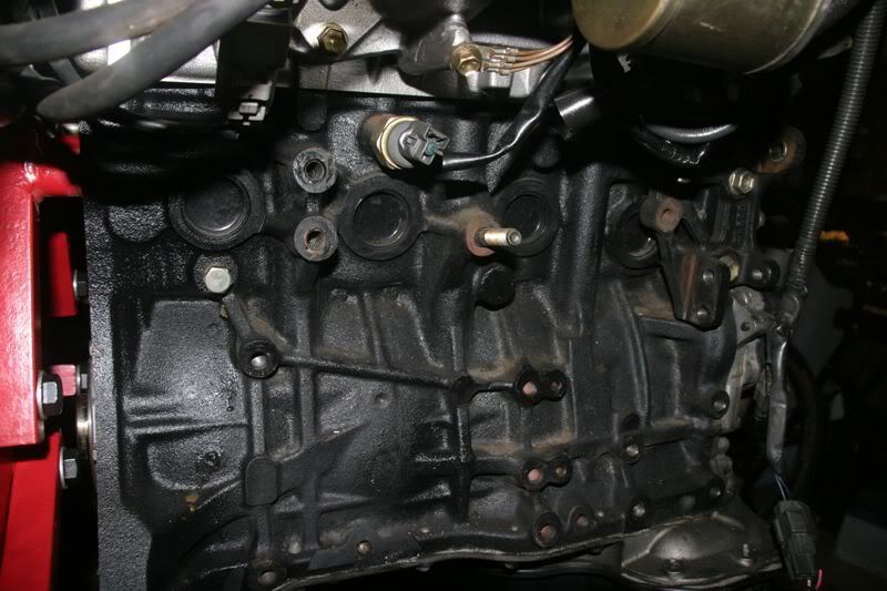
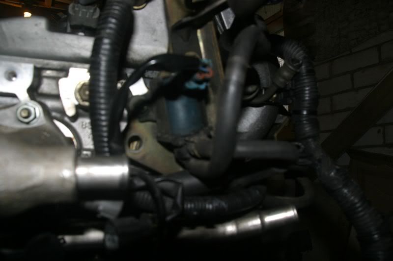
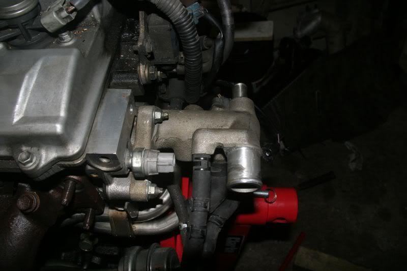 Round the back it's immediately obvious the knock sensor has moved
Also note the shiney bolt middle left. This goes directly into the water jacket. I can't remember if the 205 block has such a drain or not
Round the back it's immediately obvious the knock sensor has moved
Also note the shiney bolt middle left. This goes directly into the water jacket. I can't remember if the 205 block has such a drain or not
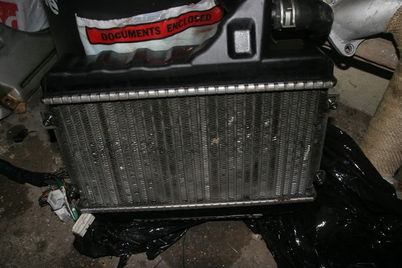
 Top mount intercooler. Significantly better than the 185 setup, bigger and thicker. Also equipped with plastic tanks
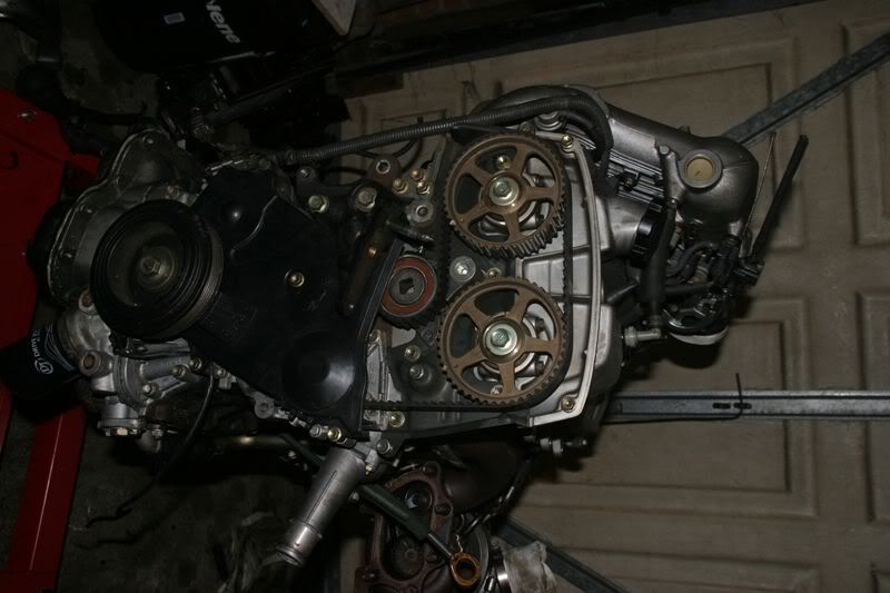
Front of the engine looks familiar. Note that the cambelt tensioner pulley is different with a 1/2" square drive in the centre for some reason
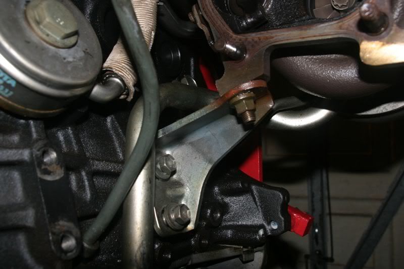
 Turbo support bracket is a much more sensible steel affair compared to the ST205 braacket which is hewn from solid heavy
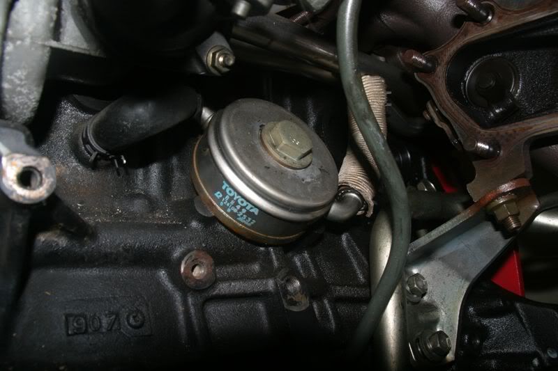
Doughnut oil cooler is redesigned but still present on the 215. On the ST245 caldina it's gone!
 The sensor in the middle is the TPS (Turbo Pressure sensor) which is now directly bolted to the manifold not the firewall
[img]
The sensor in the middle is the TPS (Turbo Pressure sensor) which is now directly bolted to the manifold not the firewall
[img]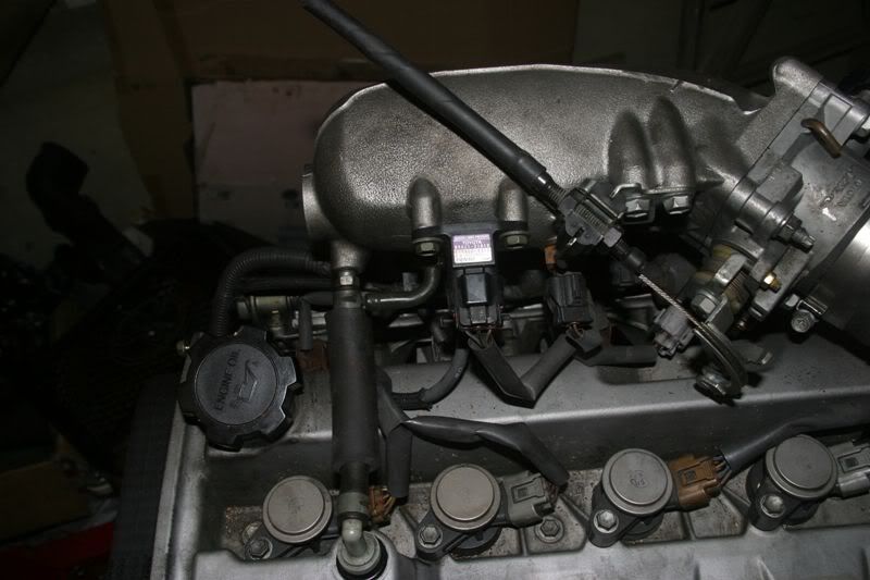
Where the dizzy would normally be is now the location for the turbo VSV control unit
Which is also attached to this resevoir on the rear of the manifold. Presumably this provides a smooth pressure despite the PWM action of the VSV controller
Front of the throttle body. Note the ISC attached to the bottom. It appears to be the same as that used on the 205 complete with throttlebody heating circuit
[img]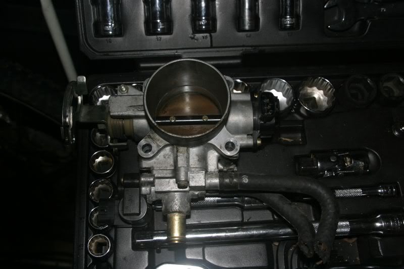
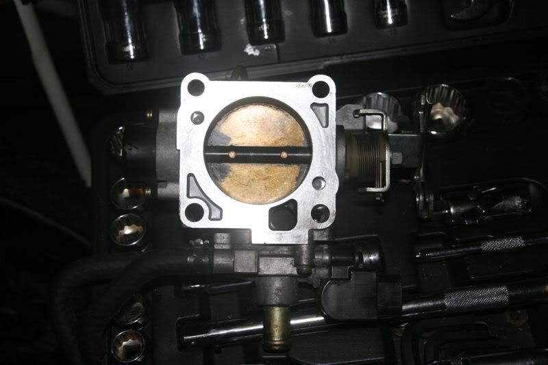
Rear of the throttlebody. Not dissimilat to the 205 unit
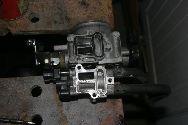
Disassembled IAC control block. You can see the barrel "throttle" of the ISC and you can also see that the manifold heater is just a very short direct connection channel. It does not go round the TB in any way
4 layer exhaust manifold gasket is made up of 4 single identical steel gaskets
[img]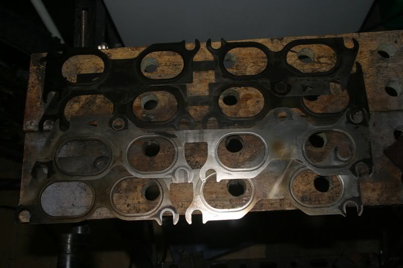 [/img]
Head exhaust ports and stud pattern appear identical to a st205 head
[img]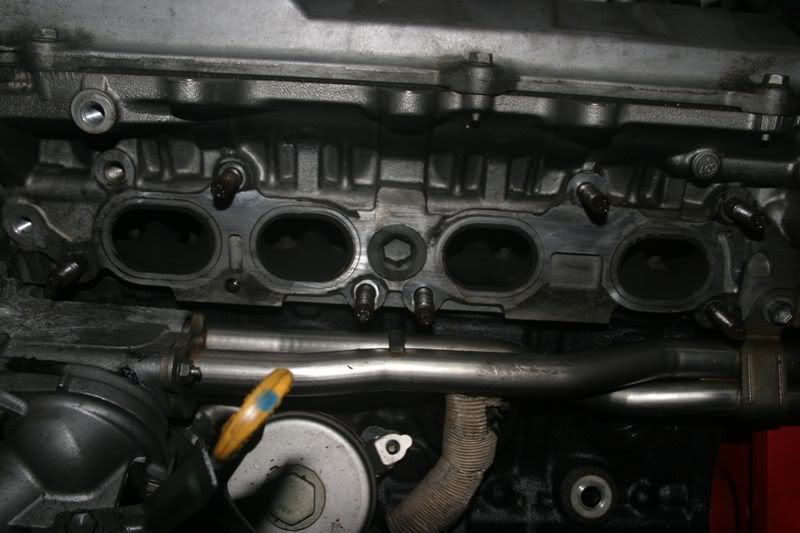 [/img]
Note the change to a "log" manifold. On the 205 manifold there's some separation of exhaust to make the twin scroll turbo work. On the 215 all the exhaust ports are conected into a single pipe. I'm certain this means no twin scroll
[img]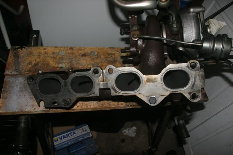 [/img]
Once the turbo VSV resevoir has been removed another VSV is immediately visible....more later
[img]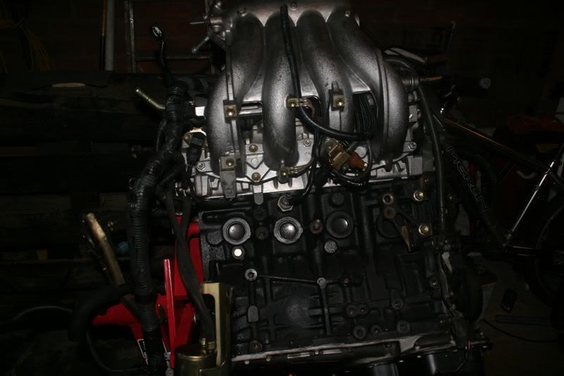 [/img]
[img]
[/img]
[img]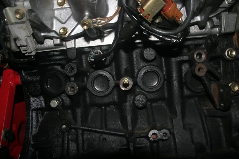 [/img]
Off with the inlet manifold then. You can clearly see that the 215 has switched back to top feed injectors a la ST165
[img]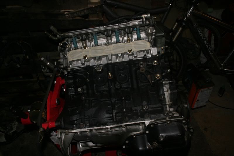 [/img]
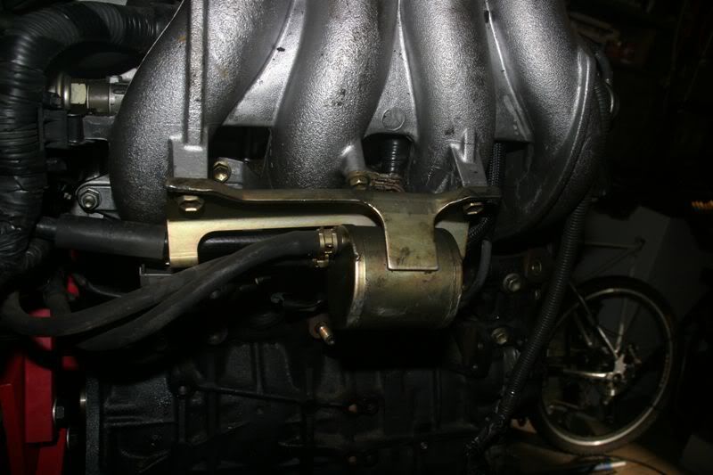
Fuel return and FPR
[img]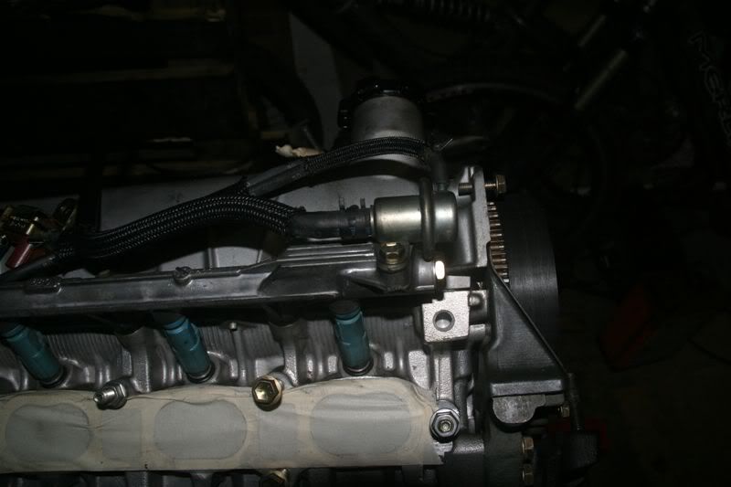 [/img]
Fuel feed
[img]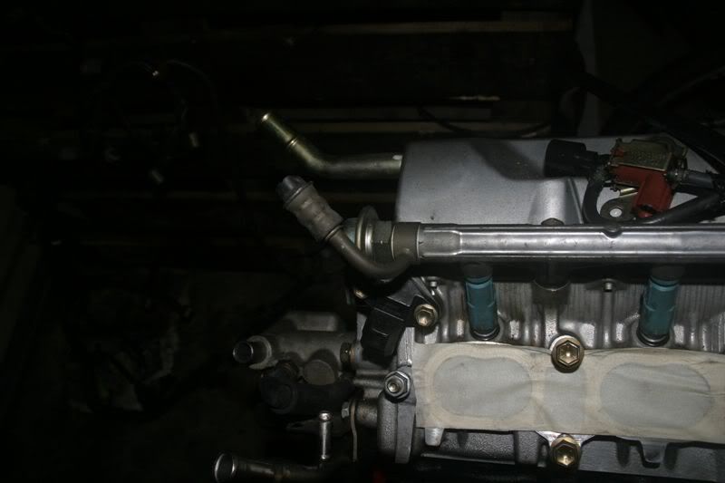 [/img]
The rail is perfectly set up for a fuel pressure gauge. The large nut undet the FPR is removable and directly accesses the fuel rail :D
[img]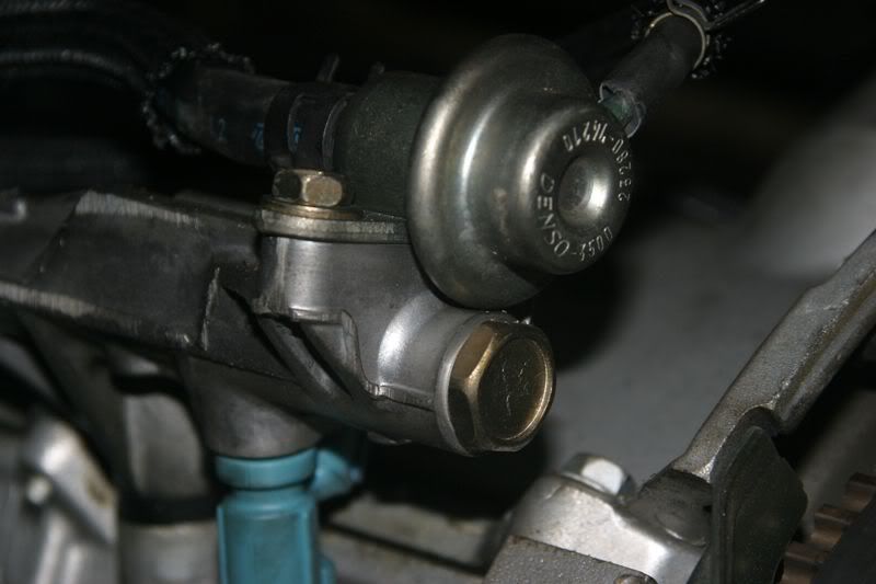 [/img]
With everything out of the way you can now see that the FPR is connected to the VSV that was on the back of the inlet manifold. I assume this does away with the fuel pump resistor but I don't know for sure
[img]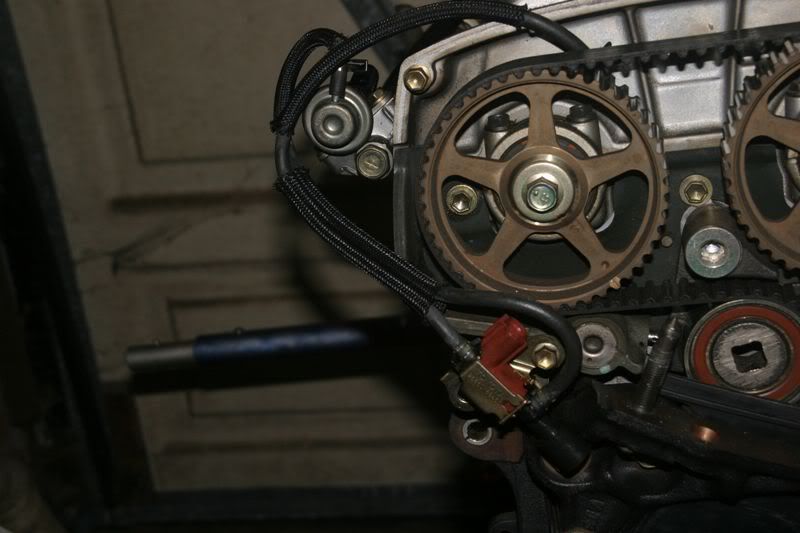 [/img]
It's a bit of a poor photo but you can actually see right through the fuel rail if you look hard. Internal Diam of the fuel rail is ~10mm. It's a pretty good looking rail for high power
[img] [/img]
Coil on plug packs :D :D
[img]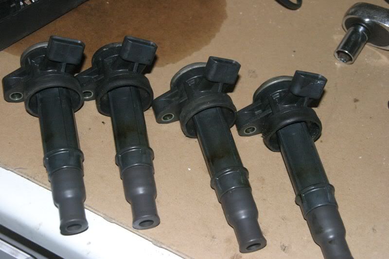 [/img]
A vital part of the coil on plug setup. With no dizzy you need another cam position sensor. This is it and it's great news for me :D. The "trigger wheel" is attached to the end of the inlet camshaft. You can also see the sensor in the background
[img]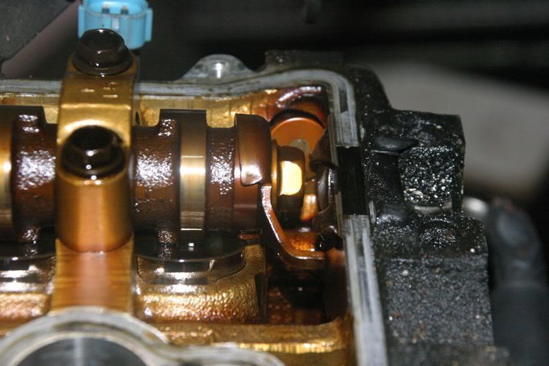 [/img]
The cam sensor is simply bolted on in place of the dizzy. This means the nice 264 cams in Hannibal should work fine with the system (they might need a bolt hole drilling but that's apparently it)
You can also see the blank used to dispense with the dizzy shaft. This one is clearly well sealed then :roll:
[img]
[/img]
The cam sensor is simply bolted on in place of the dizzy. This means the nice 264 cams in Hannibal should work fine with the system (they might need a bolt hole drilling but that's apparently it)
You can also see the blank used to dispense with the dizzy shaft. This one is clearly well sealed then :roll:
[img]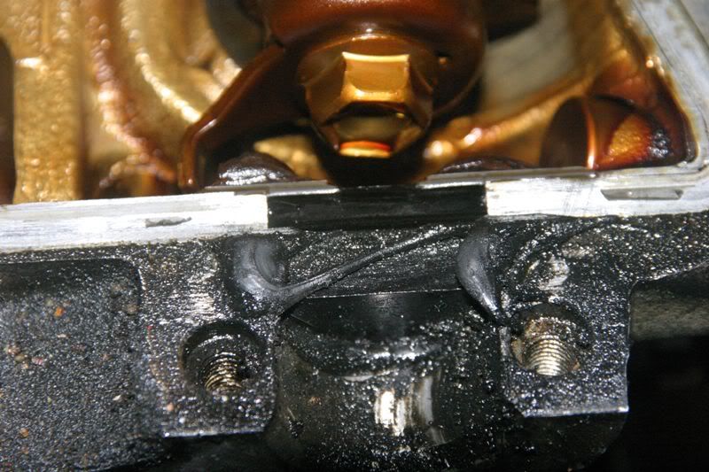 [/img]
The buckets show no visible wear. I think this might be a genuine low mileage engine :shock:
[img]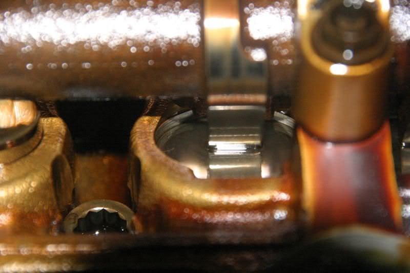 [/img]
Nothing unusual here except....The cam cover has an inbuilt catch can type setup. The baffle plate should condense any oil out
[img]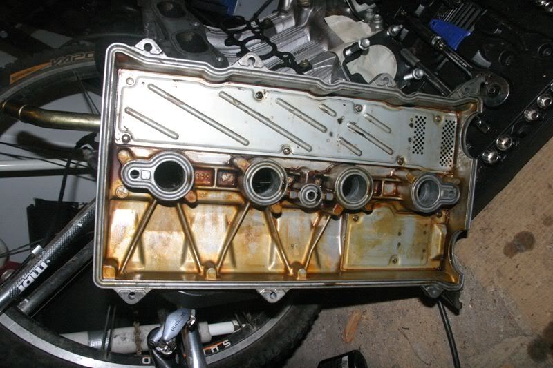 [/img]
And the view from abovu. Note lugs to secure the COP units and a return to a 185 style breather position
[img]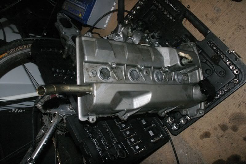 [/img]
Better view of the distributor replacement plug with several feet of leaky crud removed
[img]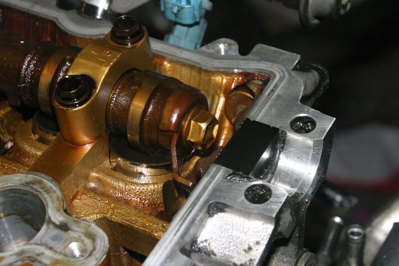 [/img]
Gratuitous photo of things to come for Hannibal. GT3071 with (eventually) external remote wastegate :twisted:
I'd really really like to turn the turbo the other way up though ;)
[img]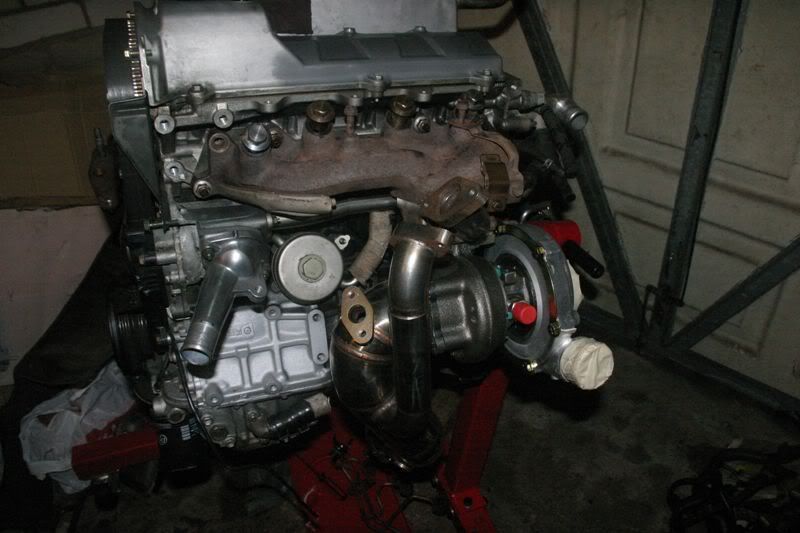 [/img]
A few closeups of the combined mani/turbo setup. Note the hulking great single wastegate. Boost creep should not be an issue on the Caldina :D
[img]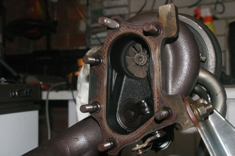 [/img]
[img]
[/img]
[img]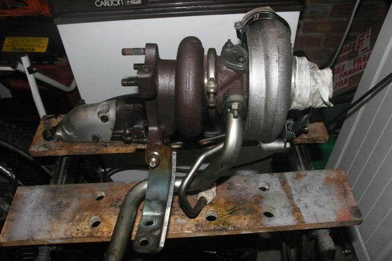 [/img]
[img]
[/img]
[img]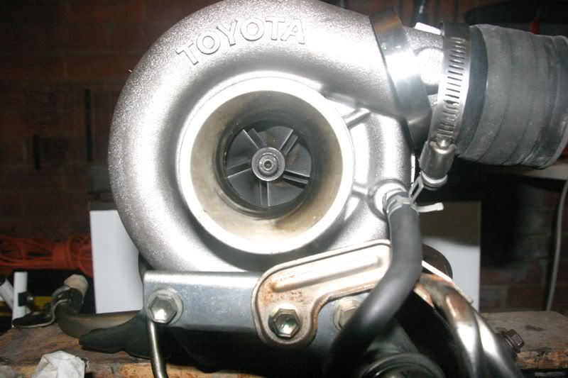 [/img]
And over we go :lol:
After an hour of unsuccessful panning for gold in the metal sump, off with the main sump section. Nothing bad looking here. The usual 3S-GTE varnishing but nowt unusual. This really might be a low miler. Time will tell
I wonder if my warranty is still valid :lol:
[img]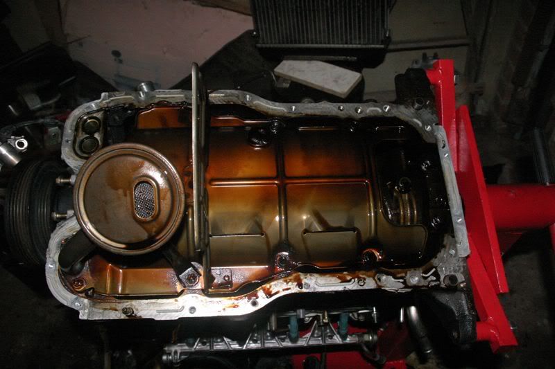 [/img]
Scraper plate removed and block face cleaned ready for a nice new bead of sealant. Nothing looks out of place or different here
[img]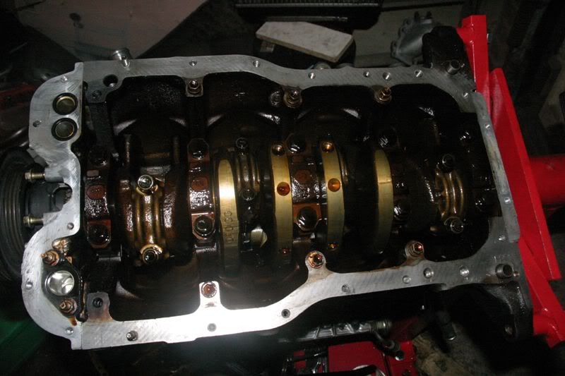 [/img]
A poor picture but you can just about make out the oil squirter underneath the counterweight
[img]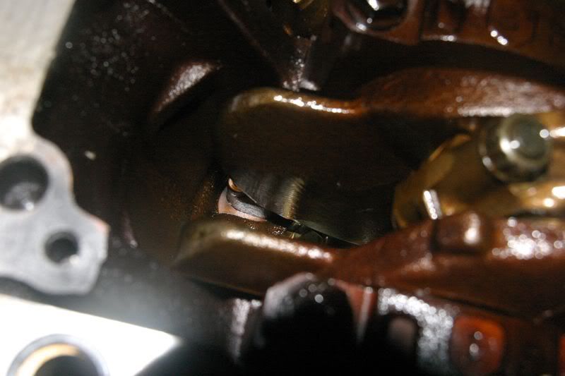 [/img]
- lol:I hope you're reading this Don :lol:
Part 2 of the COP setup. You can see a crank trigger wheel built into the cambelt drive puley
[img]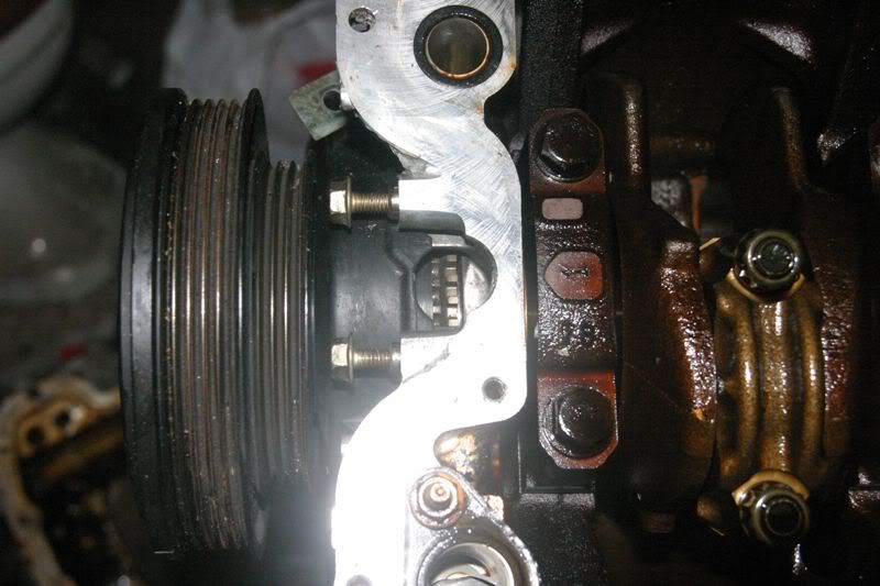 [/img]
And here's the sensor that actually picks up on that trigger wheel giving a high resolution crank angle sensor unlike the 12 tooth version in the stock ST205 distributor setup
[img]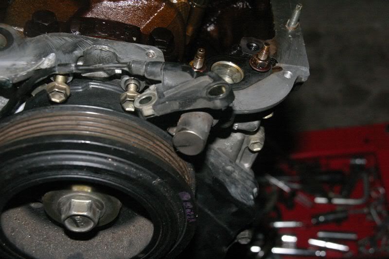 [/img]
So it turns out that a 12mm shoulder drive socket fits the ARP-a-like rod nuts. It wasn't pleasant trying to unwind the first one even though the socket seemed to fit fine :lol:
No1 Main bearing and No1 Big end. Main bearing shows minimal wear, big end not showing too much either
[img]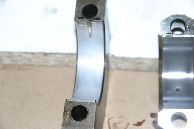 [/img]
Crank is shiney new but doesn't look it in the picture due to the oil on it
[img]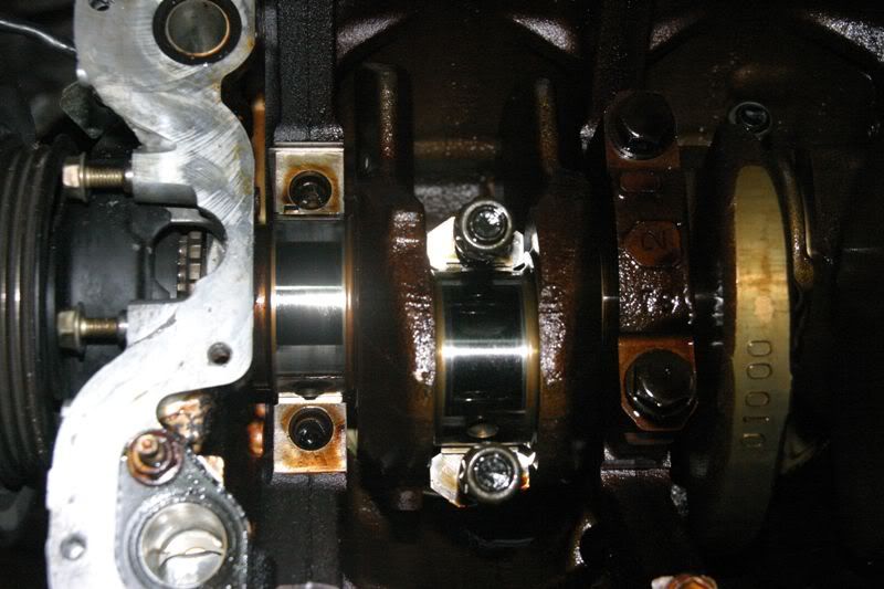 [/img]
Number 5 main bearing and number 4 big end. The main doesn't even look broken in, big end shows some wear but not drastic
[img]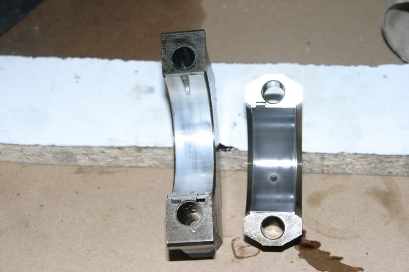 [/img]
Again the crank journals look brand new under the oil
[img]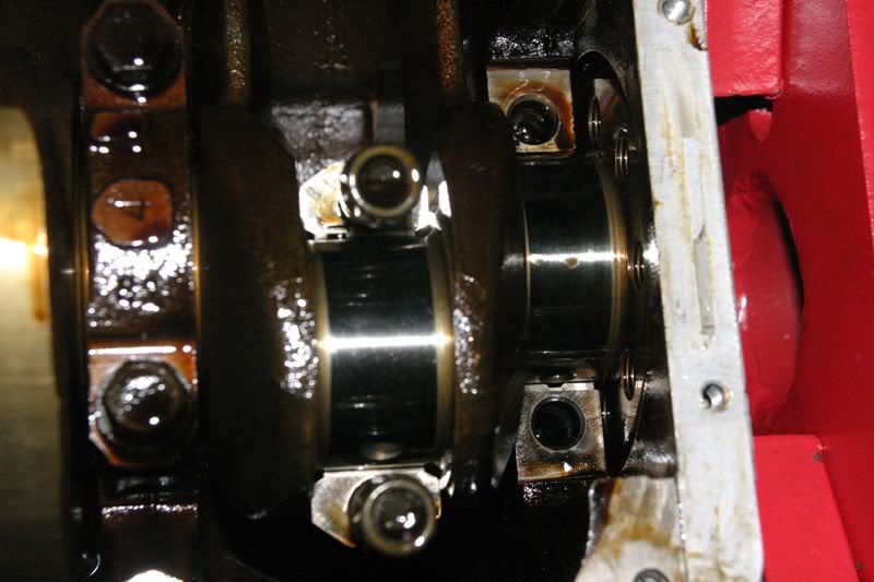 [/img]
Number 2 main and big end. Again, little wear evident
[img]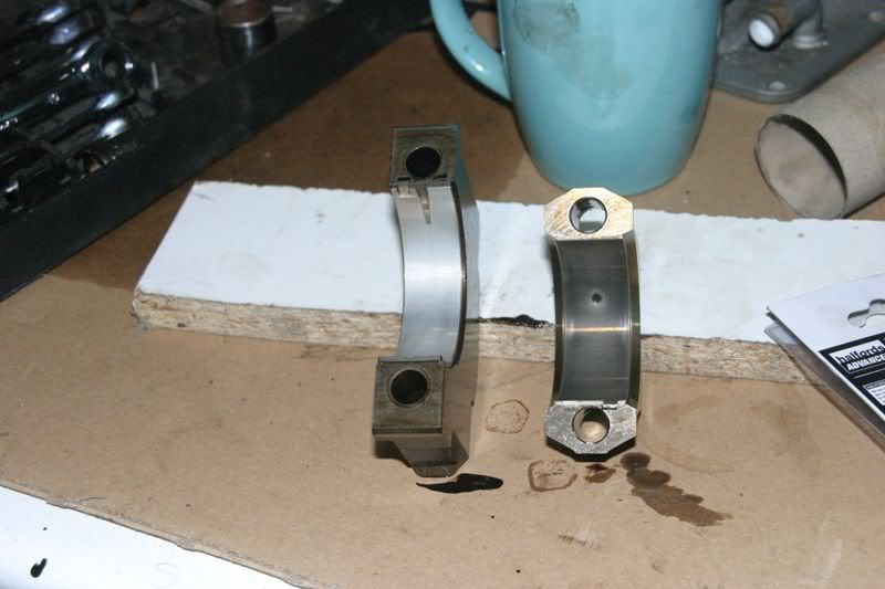 [/img]
Number 3 "central" main and number 3 big end. Being the super wide bearing the main looks brand new. Big end has minimal wear
[img]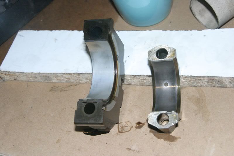 [/img]
The thrust bearings are the only set showing any real wear. Struck me as odd as the donk is from an auto so I expected less side thrust than a manual with clutch
[img]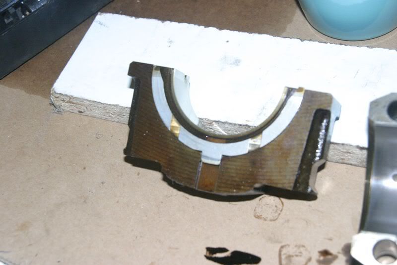 [/img]
Number 4 main, again looks brand new
[img]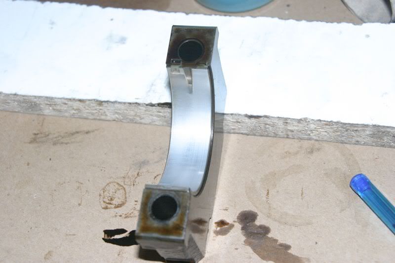 [/img]
Overall everything is showing very minimal wear. At this point I'm just going to order up a new set of original size bearings from Mr T and that will be that. There's nothing visible that makes me think the tolerances wont be as new this way
The block journals are 1 2 2 2 2 and the crank is 0 1 0 0 0 Both pretty consistent. Original bearings, as expected, are 1 3 2 2 2
Big ends are all size 2
Crank pulley removal. I forgot to photo the crank nut undoing procedure. A favourite method seems to be a block of wood thrown in the crankcase to wedge up the crank. Im not a huge fan of this. Instead I wound a couple of bolts into the flywheel drive plate and used the olf favourite crowbar between two bolts trick jamming the bar against the engine stand
Just for a laugh I decided to forgo the crowbar and twat it with a gurt hammer than so many people use to get the pulley off (judging by the number of chipped pulleys I've seen :( ). Instead I dug out a genuine puller. The crank pulley is conweniently provided with 2 bolt holes to allow this :)
[img]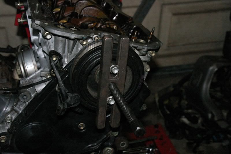 [/img]
Timing belt also looks brand new
[img]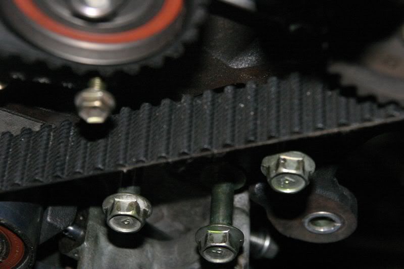 [/img]
Just for JP, part number 90919-05034 bolts on here like this
[img]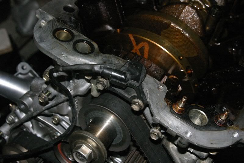 [/img]
And picks up the trigger wheel shown more clearly here
[img]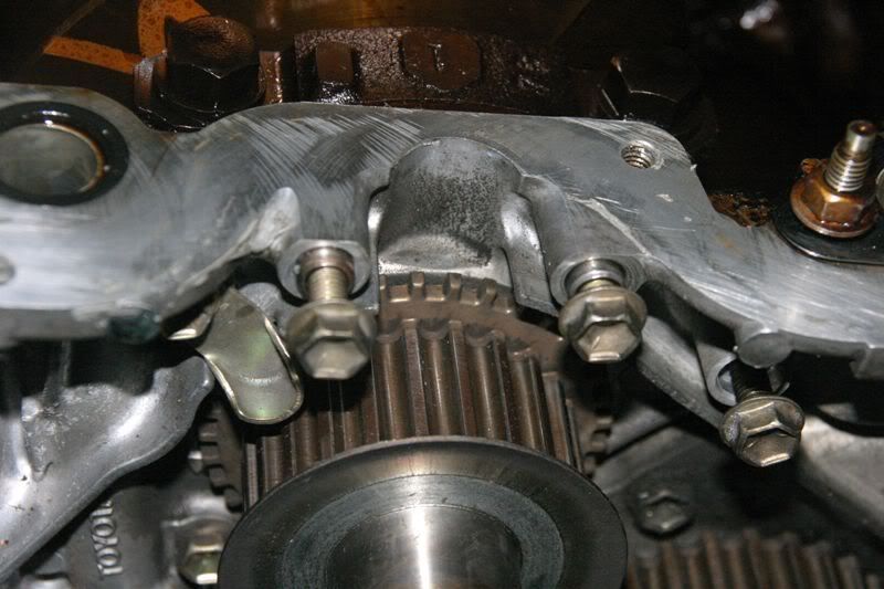 [/img]
Hey, that's handy. The 1/2" drive socket in the idler pulley means you can use a 1/2" drive ratchet (or torque wrench :lol: ) to slacken the tensioner enough to remove the belt
[img]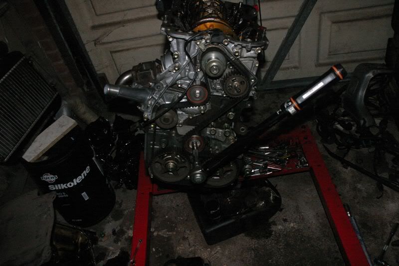 [/img]
And with the aid of a thin bar you can actually reset the tensioner and insert the pin without resorting to stuff in vices.
[img]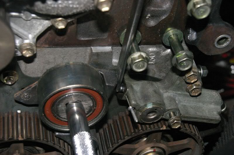 [/img]
One thing to remember.......Undo the oil pump pulley before removing before removing the cambelt. Otherwise, re-assembley is the reverse procedure to get the belt back on
Water pump removed. Yawn, it looks almost new although there is a tiny bit of float in the bearing
[img]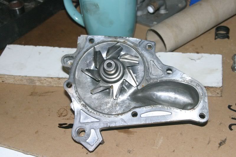 [/img]
Oil pressure relief valve. Minor varnishing but predictably otherwise new looking
[img]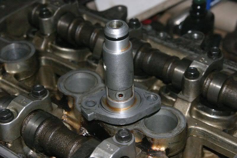 [/img]
Project for tomorrow. This head needs to be stripped ready to be dropped off with the man who'se going to give it once over for me. It'll be getting new stem seals for sure and guides and a skim if needs be (assuming it's not scrap lol)
[img]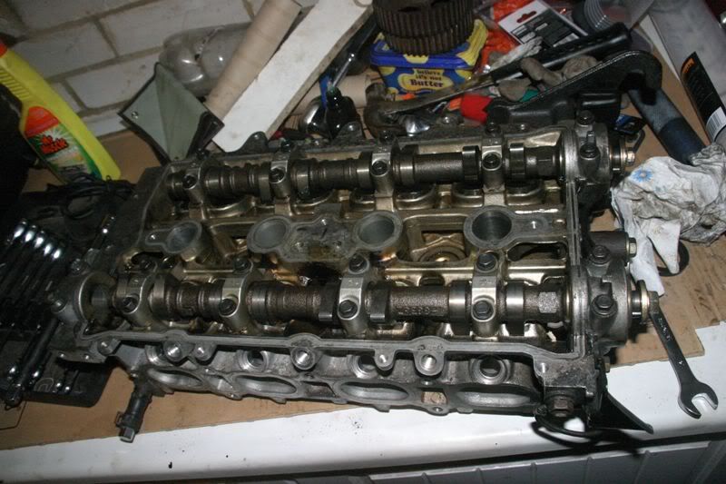 [/img]
So, overall sitrep.....
I do genuinely believe that this is a low mile engine as advertised. Given that it's off eGay I didn't necessarily expect this. I could have pretty much plonked it in without anything to worry about on the bearing front. Still need to whip the head off and check the pistons but I'm hopeful they'll be OK
As it is it will get new bearings all round, new oil and water pumps, pressure regulator, cambelt, idlers etc etc Even though it doesn't really seem to need them it would seem daft to me not to replace all this stuff. The engine should hopefully then be tool free until the next cambelt service is needed
BAH,
Spent hours looking for valve spring compressors, various other tools and the box of ziplock bags I bought ages ago. Unsuccessfully :(
So, back to good old catch it a gurt smite with 'ammer methods then :lol:
Skip the next photo if you're feint hearted
Once you've removed the bucket the spring seat and collets are looking at you (the shim sticks to the magnetic bucket ;) ). Place a 19-20mm socket on the spring seat and........... SWING (not too hard, start reasonably gently)
[img]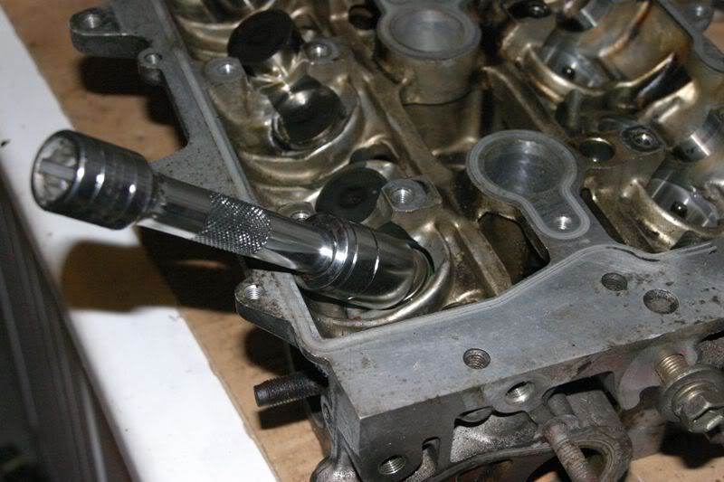 [/img]
If all goes to plan the collets will jump out of the valve grooves and the springs are released, leaving you with the bits below. The socket should contain all the flying bits. If all doesn't go to plan you'll either have a black thumbnail or there's a valve spring embedded in the roof and the collets have flown south for the winter :roll:
Note the labelled bag. This is #8 exhaust valve bits and they all stay together.
Inlet springs are marked with red paint, exhaust with green and the painted end goes into the bucket
[img]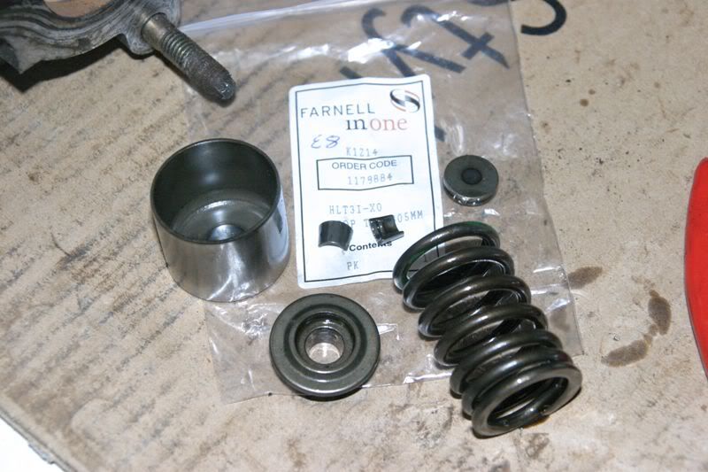 [/img]
Spring, spring seat and shim assembled as they would be in the head
[img]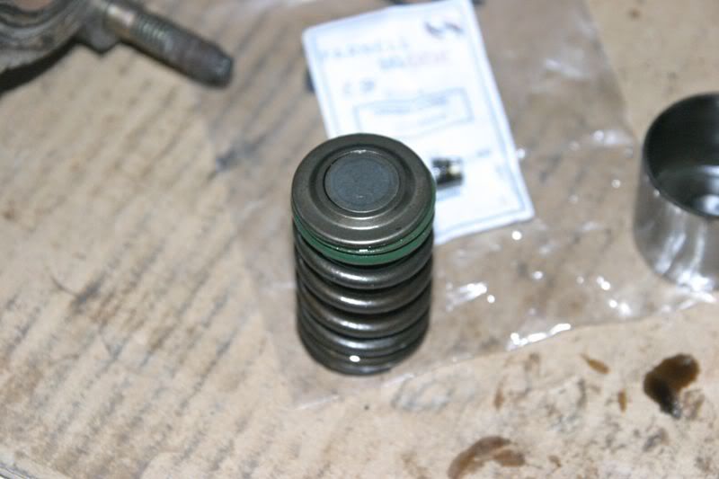 [/img]
As above but with the bucket in place
[img]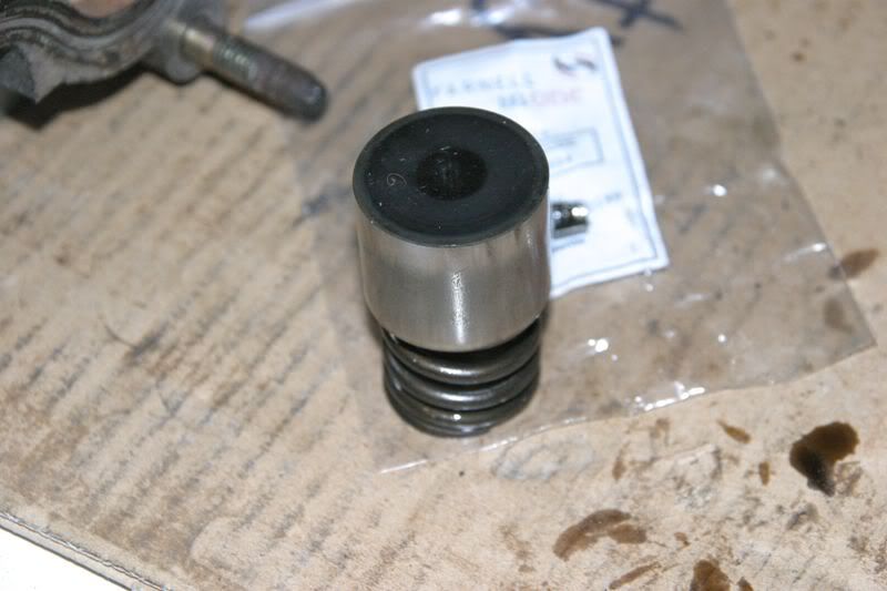 [/img]
The whole Valve "stack" as it would be in the head
[img]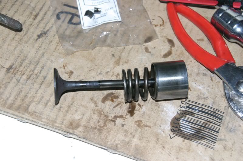 [/img]
Once all the gubbins is removed you're looking at the valve stem seal. Apparently a bit of a pain to remove without the right tools. So I didn't try :D
[img]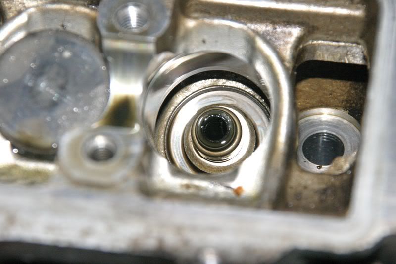 [/img]
Valves themselves are all in pretty good nick
[img]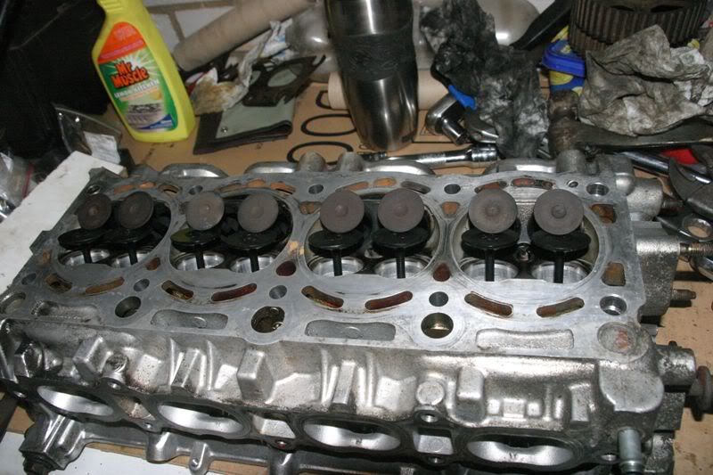 [/img]
Not much coke either
[img]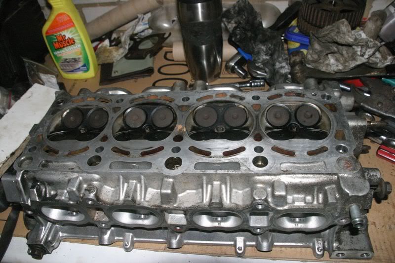 [/img]
My calibrated Wicks T square shows the head is reasonably flat but it won't actually span the entire face :lol:
It will get a skim if required
[img]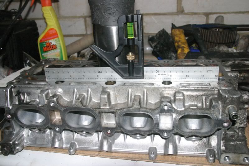 [/img]
I'm mad at mtself for this. When I bought the head a couple of years ago I checked it over and found everything acceptable. Apparently I failed to notice the two snapped exhaust studs in the middle then :oops: Thanks GTSChris :evil:
I'm reliably informed that this can be dealt with no problem
[img]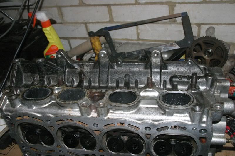 [/img]
Nicely wrapped up and ready for delivery to my local head refurb expert
[img]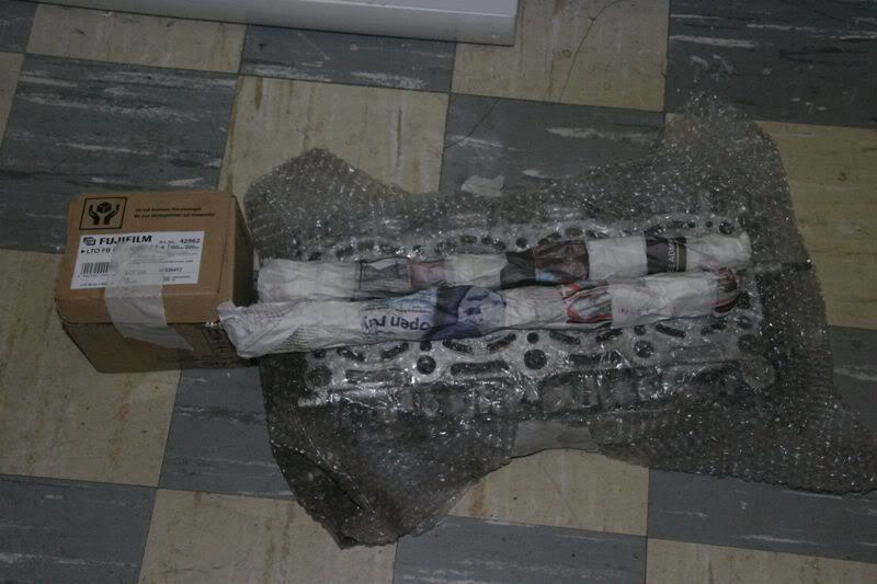 [/img]
Removing #1main bearing cap
[img]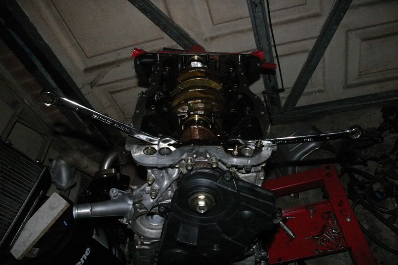 [/img]
Cap and bearing removed
[img]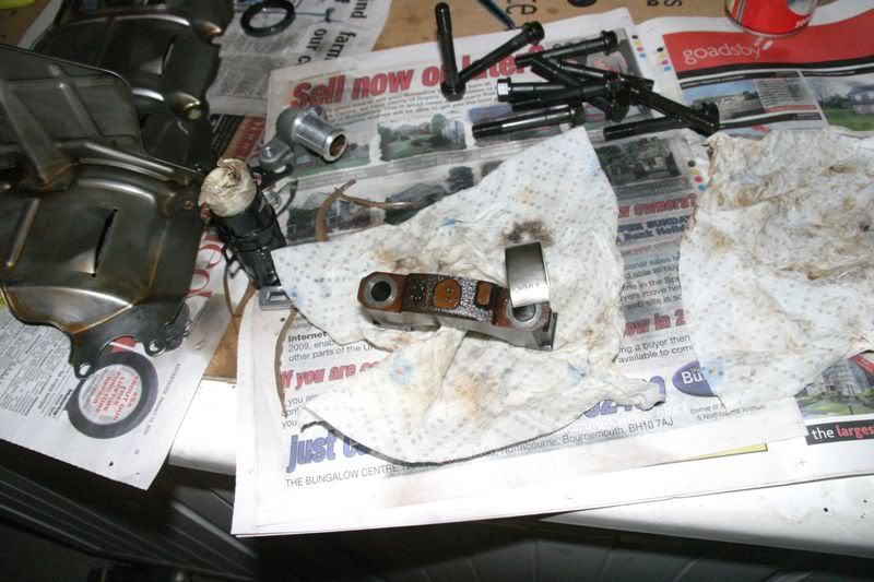 [/img]
Block bearing support sizes are atamped on the block
[img]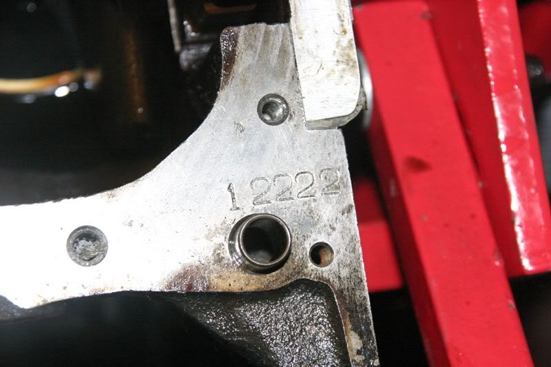 [/img]
Crank journal sizes are stamped on the crank. Add the two sets of numbers together to get the required bearing sizes
[img]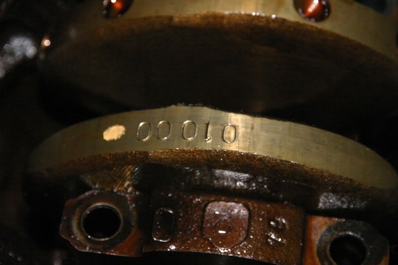 [/img]
All mains and big ends removed from the block
[img]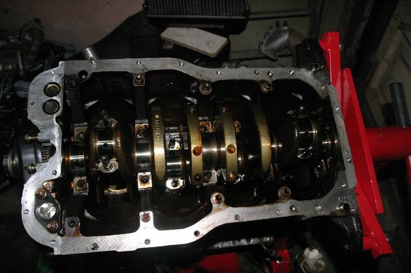 [/img]
Mains #2,3,4,5. You can see the cap number and if you squint you can see the shell sizes which tie up with the numbers on block and crank. You can also see that #3 main is larger then the others
[img]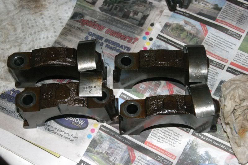 [/img]
Close up shot of crank pulley showing the missing tooth trigger wheel setup
[img]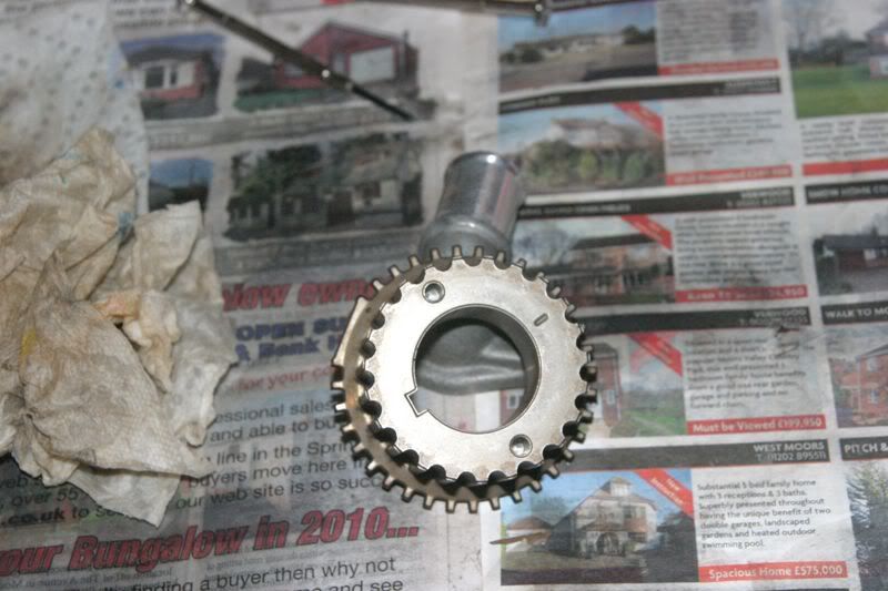 [/img]
Front of engine with oil pump removed. Starting to look a little smaller now.....
[img]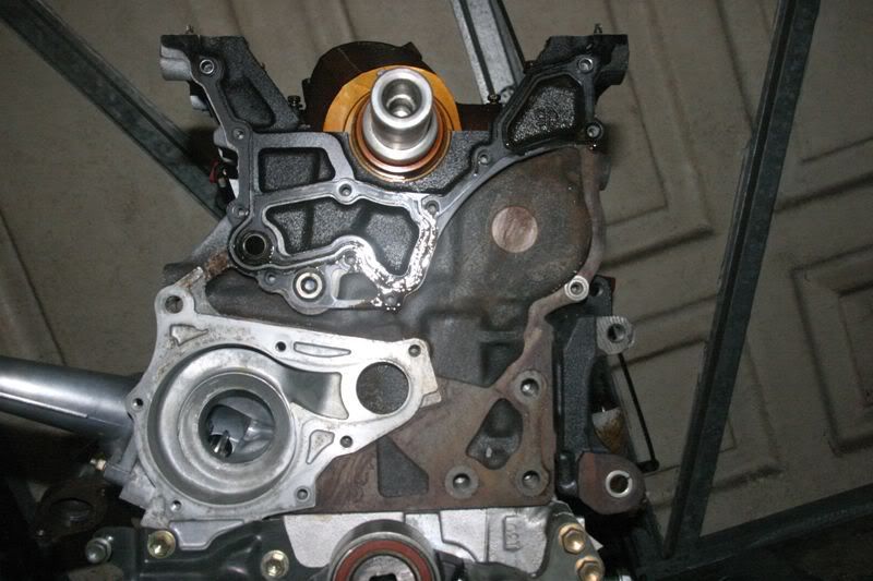 [/img]
These are the bolts that come out of the oil pump. Make sure you keep them in the right order as there's a few different lengths!
[img]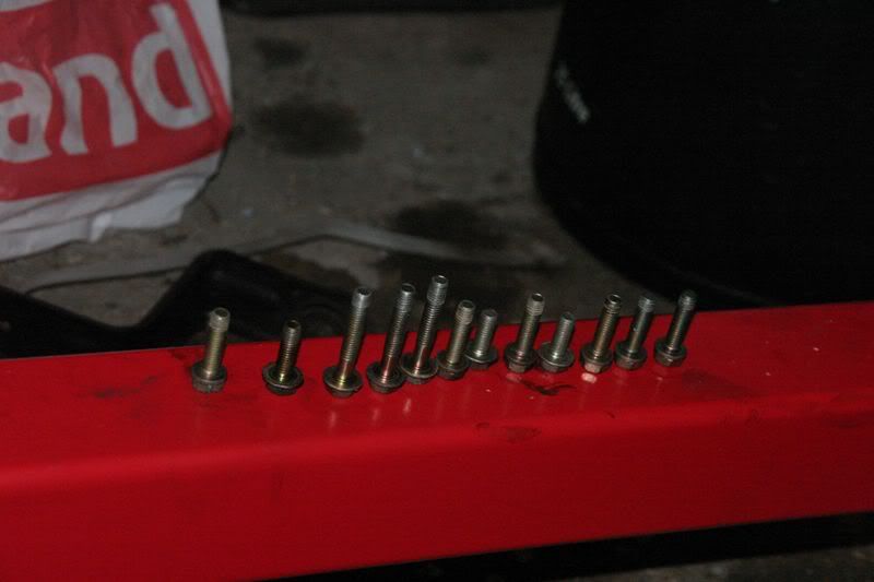 [/img]
Oil pump before going into parts washer
[img]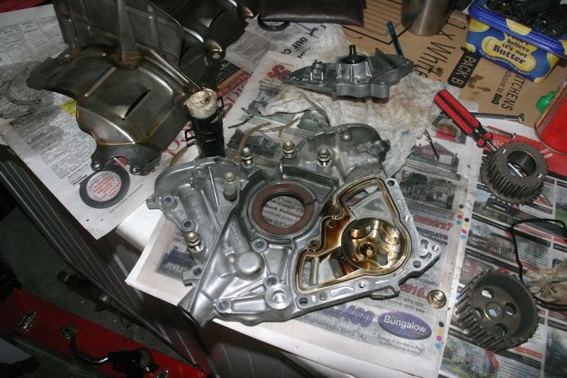 [/img]
[img]
[/img]
[img]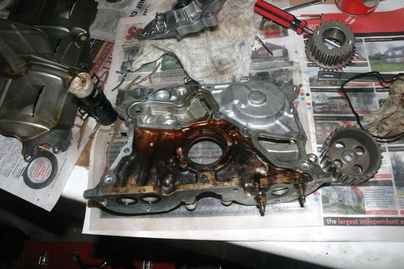 [/img]
Oil pump coming out of parts cleaner
[img]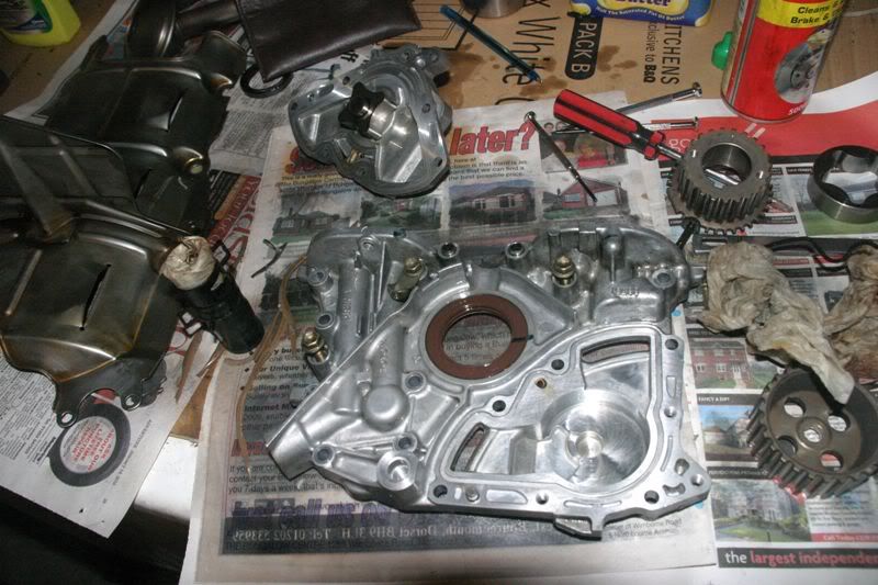 [/img]
[img]
[/img]
[img]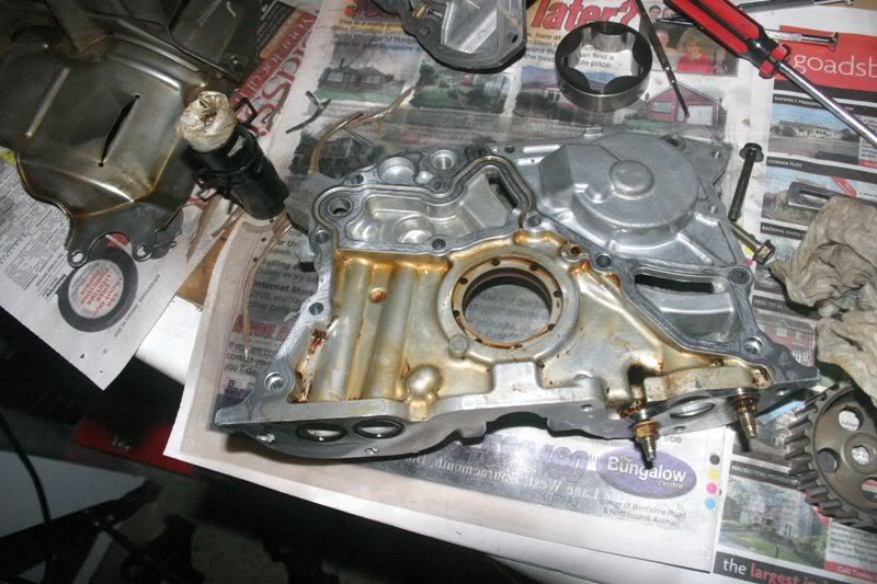 [/img]
Close up of oil pump internals. No real wear obvious on the housing or either of the two rotors
[img]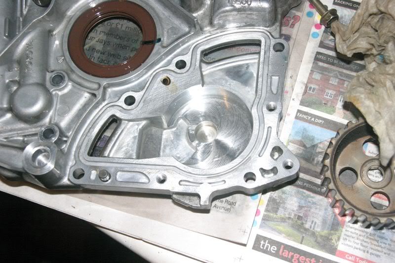 [/img]
[img]
[/img]
[img]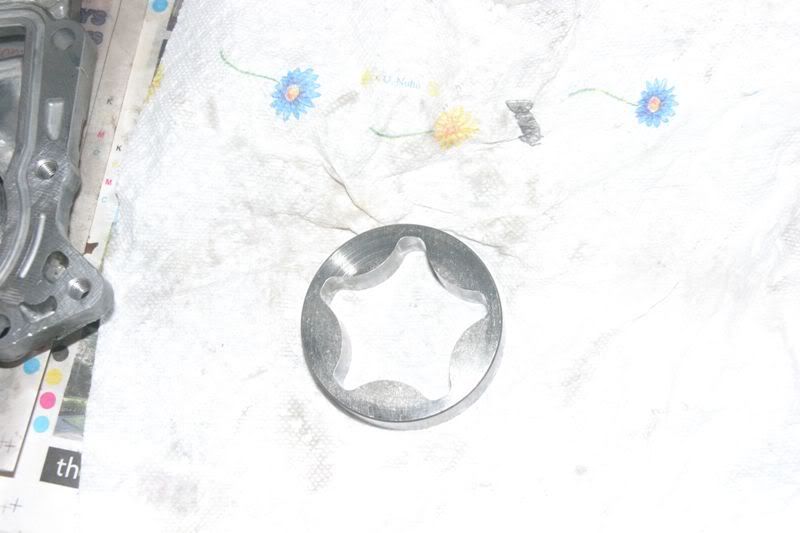 [/img]
[img]
[/img]
[img]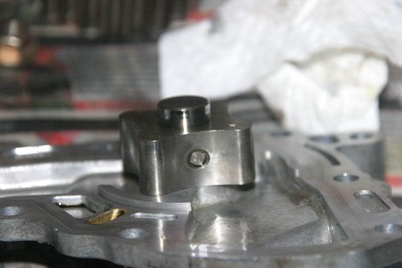 [/img]
Pump back together again. Not that any of this will go back into the engine
[img]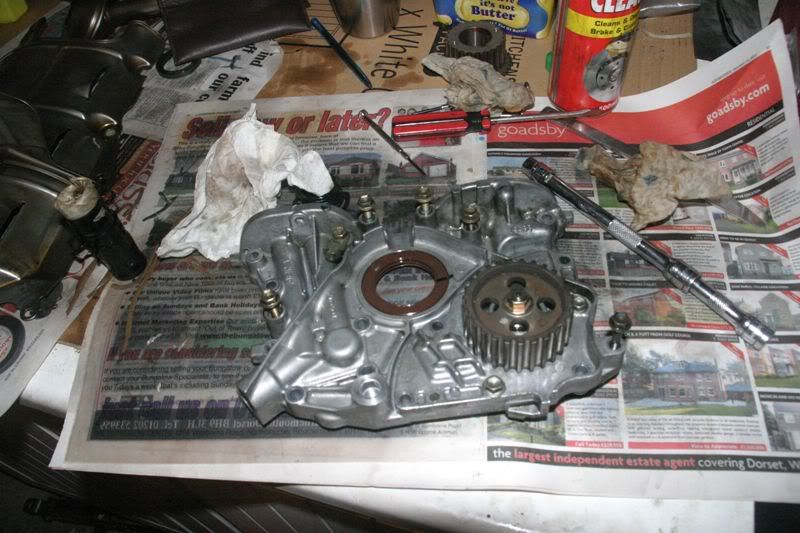 [/img]
Something missing here. Can't quite figure out what it is :lol:
[img]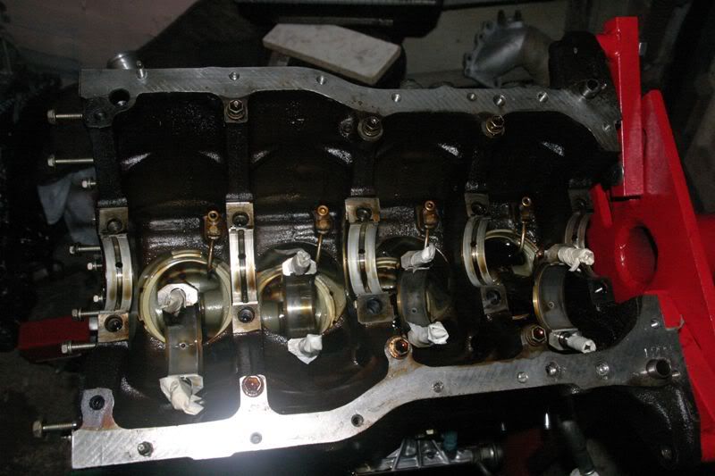 [/img]
Maybe it's this twisty wobbly thing over here? Looks a bit grubby
[img] [/img]
Into the parts washer with it. Making sure to clean out the oil drillings :D
[img]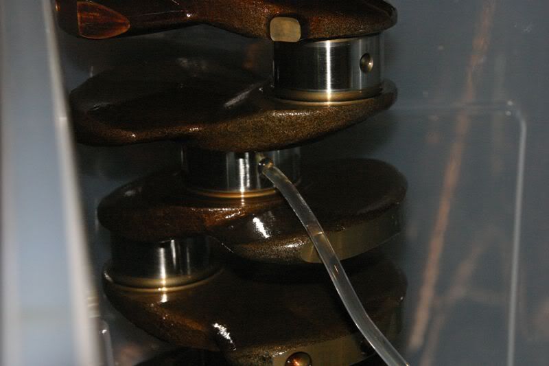 [/img]
which is achieved with the aid of this, a 205 fuel pump
[img]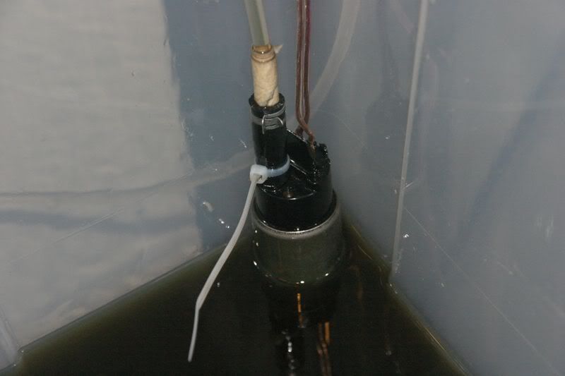 [/img]
Lashed together, er I mean cunningly engineered to produce something like this
[img]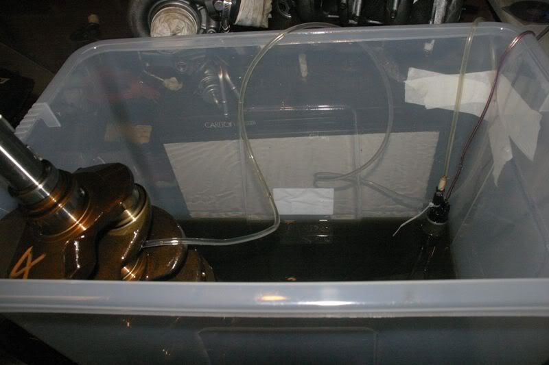 [/img]
Which results in this :D
[img]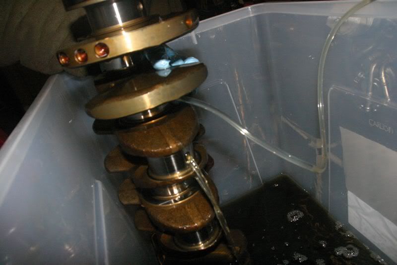 [/img]
Gearbox crank seal fresh from the washer. The actual seal will be binned so only the holder will be reused
[img]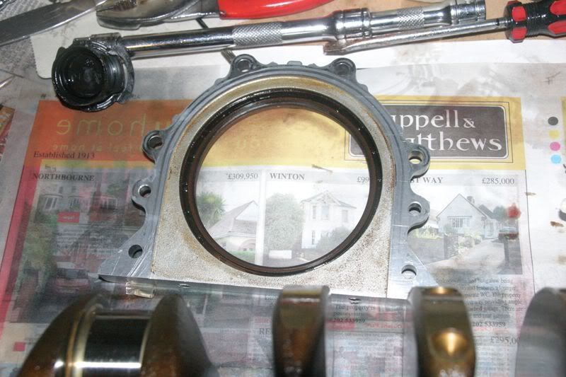 [/img]
Crank post parts washer. A little bit cleaner. I'm not going to use anything agressive to remove the oil varnish as that will likely result in more harm than good
[img]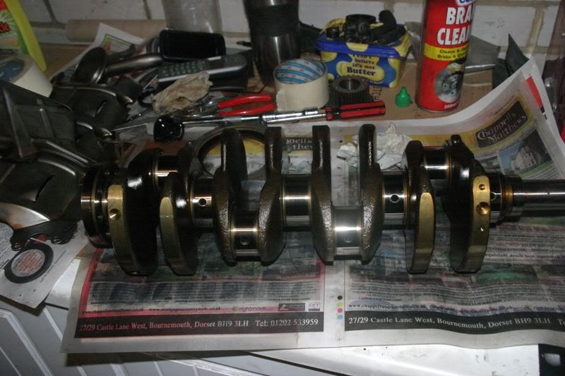 [/img]
The oil->water exchanger also feels the wrath of the parts washer of doom. Ran it for about 2 hours like this (after which the battery was dead :( ) to clean out the oil side
[img]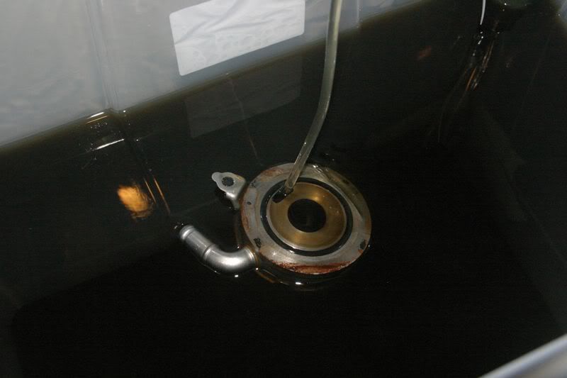 [/img]
Found this when the big valvey thing fell off the top of the block. Ignore the oil in the end cylinder. Some idiot forgot to right the engine last night so it spent the night upside down allowing the remeining oil in the sump into the head :oops:
[img]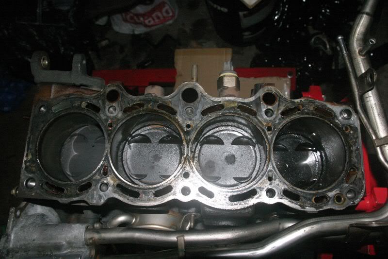 [/img]
Cleaned up a little bit. Piston crowns look OK
[img]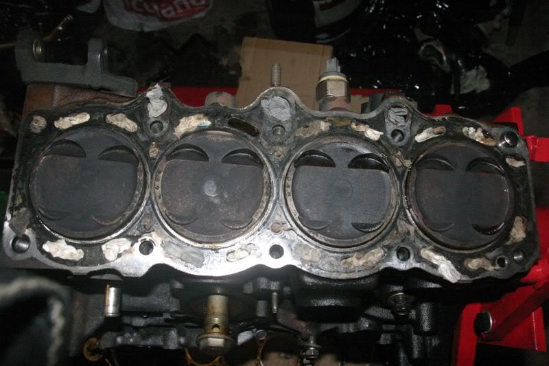 [/img]
Gave them a light clean with a scourer. Nothing bad to report condition wise. No signs of det that I can see. The 215 still has the really weak looking ringlands around the valve cutouts though :(
[img]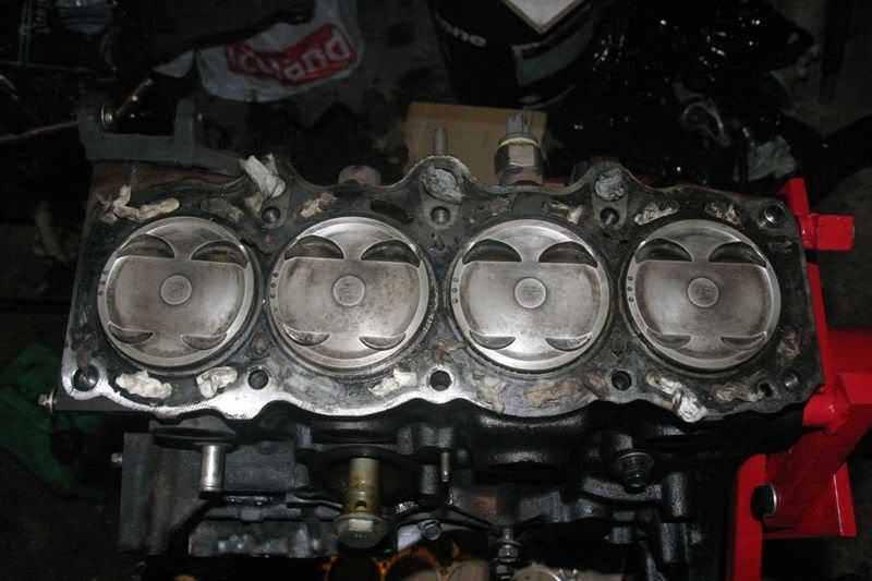 [/img]
Engine block is really looking quite small now
[img]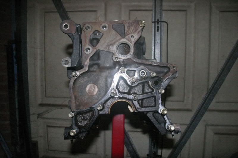 [/img]
[img]
[/img]
[img]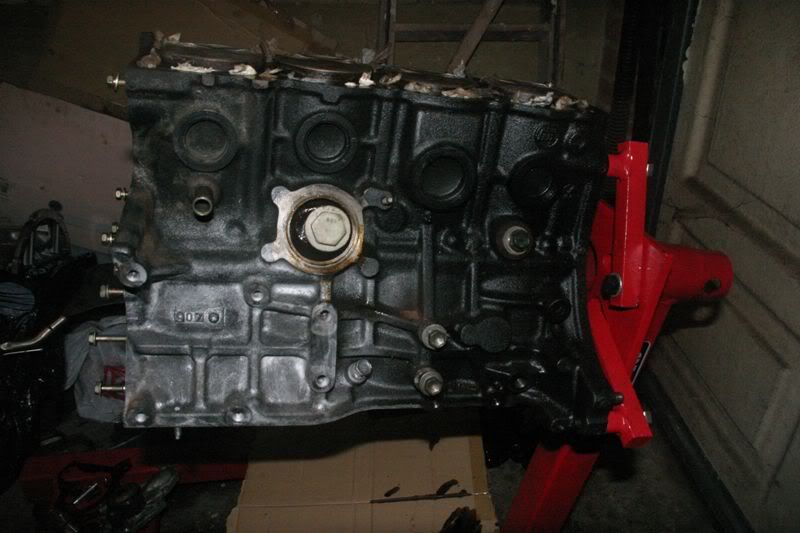 [/img]
[img]
[/img]
[img]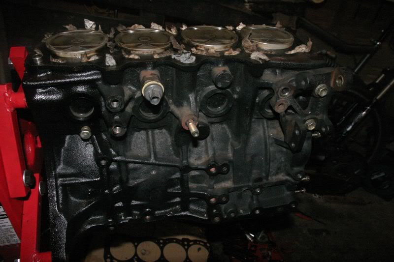 [/img]
Apart from a bit of oil around the actual combustion area the cylinder walls look fine. I'm not going to take the pistons out as the rings should be seated in their cylinders and I seee nothing that requires attention
[img]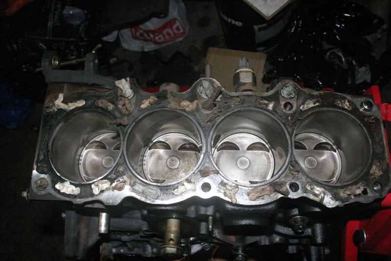 [/img]
[img]
[/img]
[img]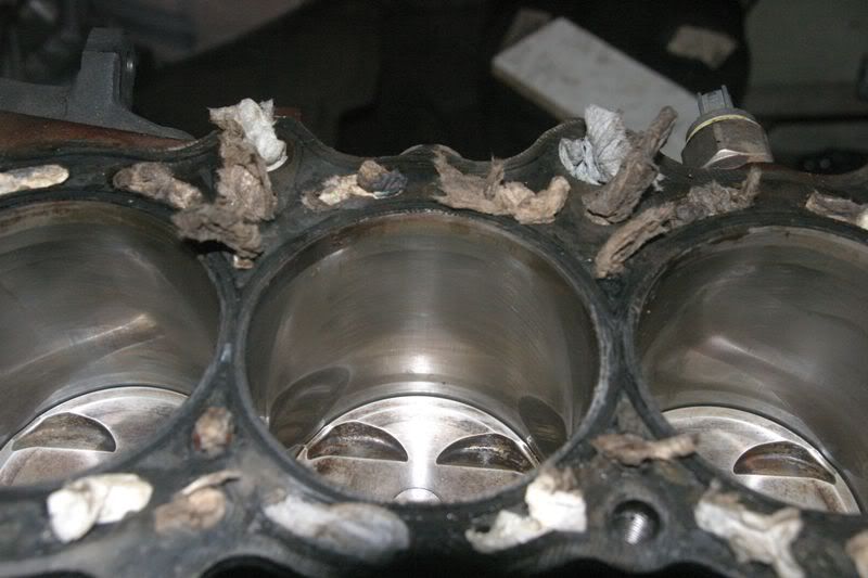 [/img]
Both sides of the head gasket. Apart from all the paint falling off the combustion chamber seals look absolutely fine. No sign of even the slightest HG failure
[img]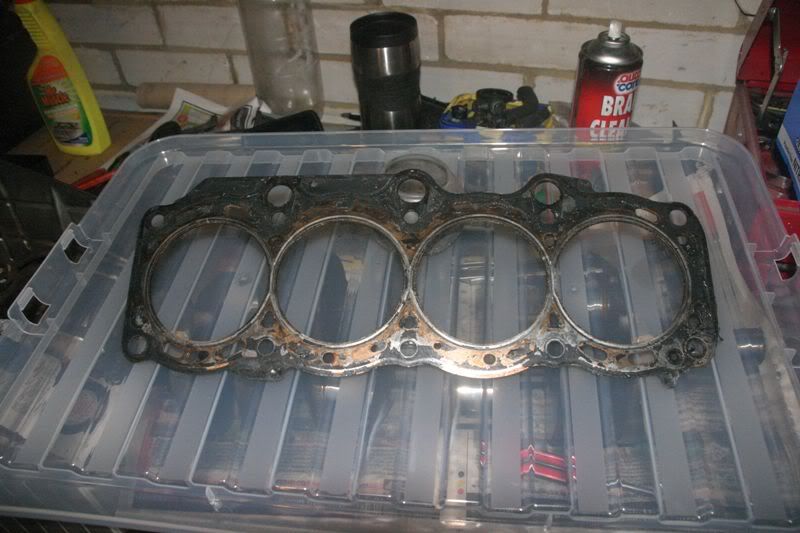 [/img]
[img]
[/img]
[img]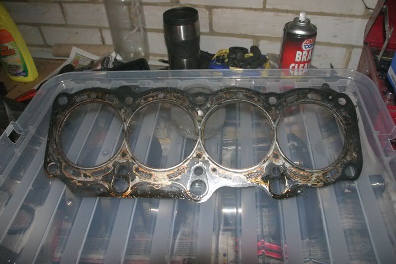 [/img]
So that's going to be about it for destruction. Hopefully Toyota will have a van load of bits in for me tomorrow and re-assembley can begin Main things that will be replaced Big end bearings main bearings water pump oil pump (complete asy) pressure regulator all seals HG cambelt, tensioned, tensioner pulley, idler pulley Clutch (eventually lol)
Can't decide whether to try and get assembley lube for the rebuild or try my usual method, EP90 gear oil. Probably the latter as I don't intend for the engine to run from dry. More on that dodge later if it works :D
Yay, finally reached the stage where the engine start to get bigger again :D :D
New plastic impeller pump (left) Vs original pump
[img]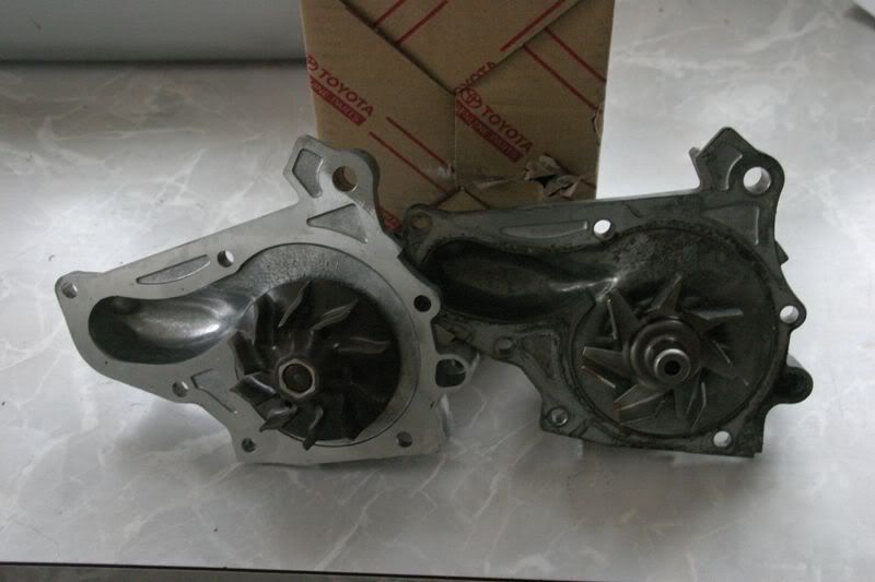 [/img]
You can just about make out the cone shape of the impeller from the blade profile on the left side of the wheel. Blades are also quite closely packed
[img]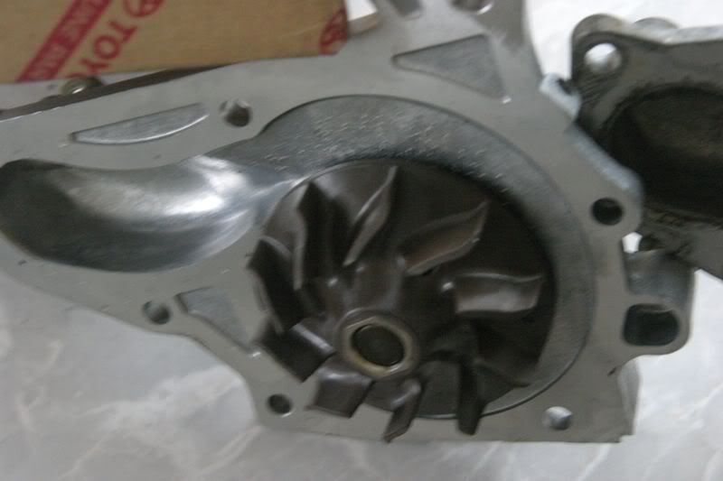 [/img]
Original pump has far fewer blades and you can see they are almost flat, not the conical profile of the new pump
[img]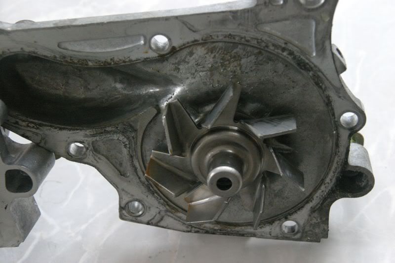 [/img]
Original pump is a type 2B? made in 2000. So the engine is newer than that :D
[img]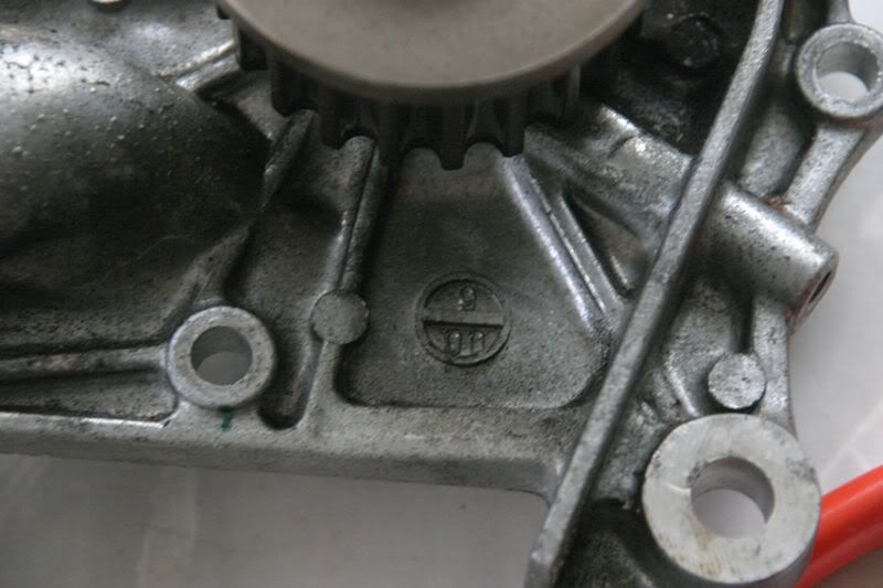 [/img]
[img]
[/img]
[img]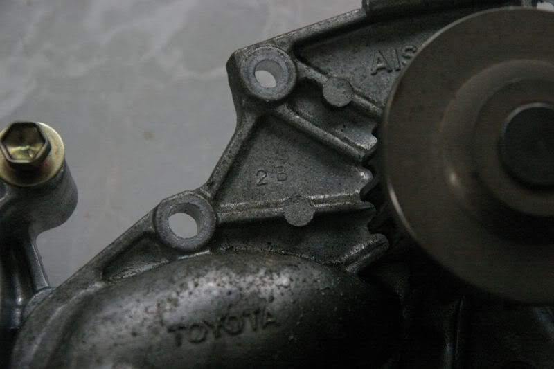 [/img]
New pump is a type 2A made in 2008
[img]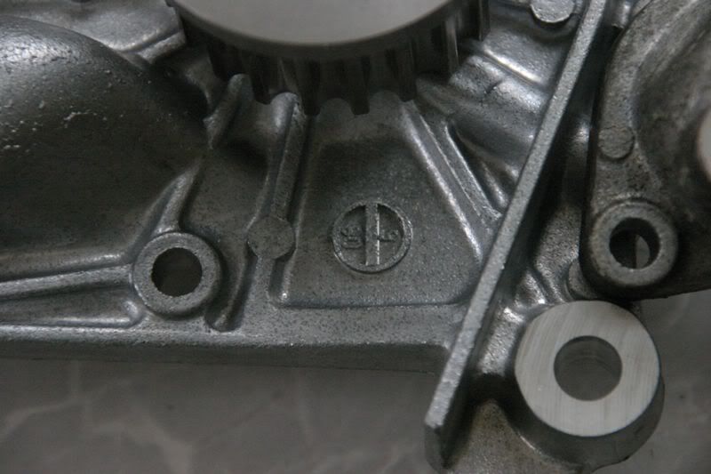 [/img]
[img]
[/img]
[img]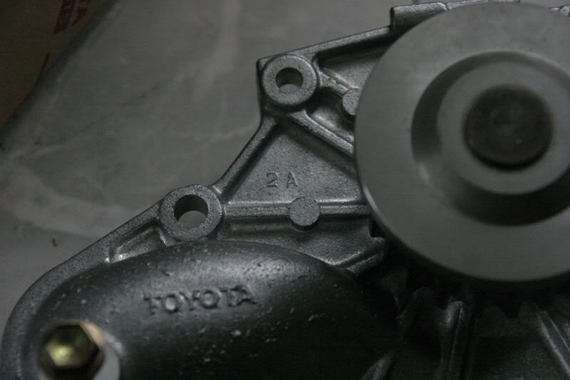 [/img]
Lots of shiney genuine Toyota bits :D
[img]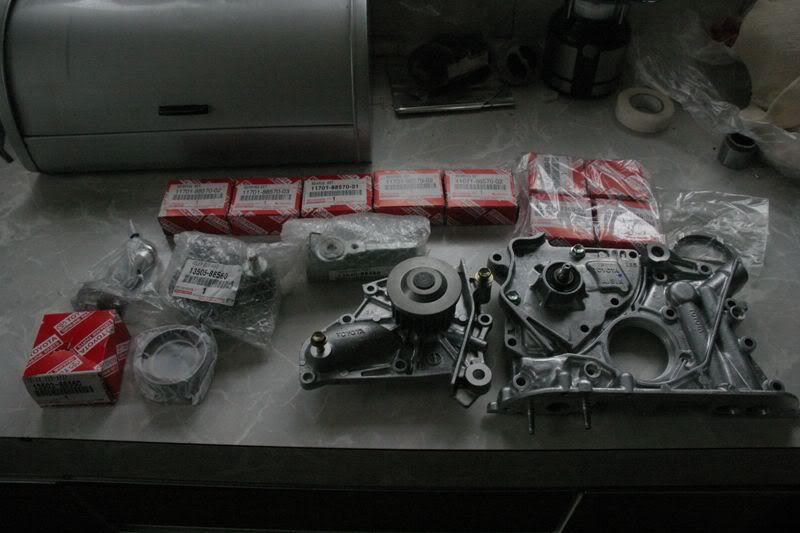 [/img]
New ST205 oil pump (left) Vs original ST215 oil pump
Taking this photo was the start of a bad feeling
[img]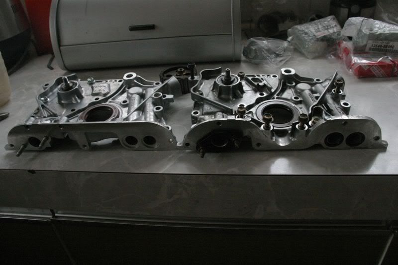 [/img]
Never seen this before (the pump is inside the cambelt covers and not visible). Both pumps have an additional port suitable for a pressure sensor
[img]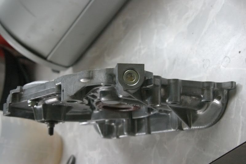 [/img]
Block cleaned, new bearings installed :D
[img]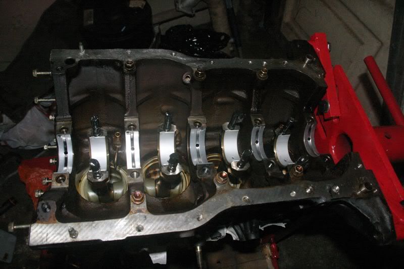 [/img]
And so begins the second round of part cleaning. The original lot was a get the worst dirt off but the cleaning fluid was too heavily polluted to call the bits that come out really clean
The solution is a mix of yellow parafin and slightly orange degreaser and clear brake cleaner which results in a lovely green soup :lol:
Everything that came out was given a final spray of neat brake cleaner to remove the parrafin residue
[img]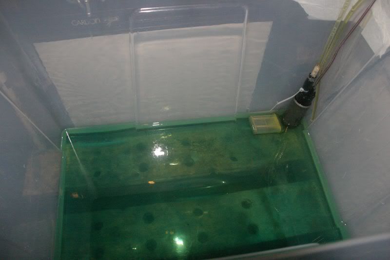 [/img]
Crank cleaned again
[img]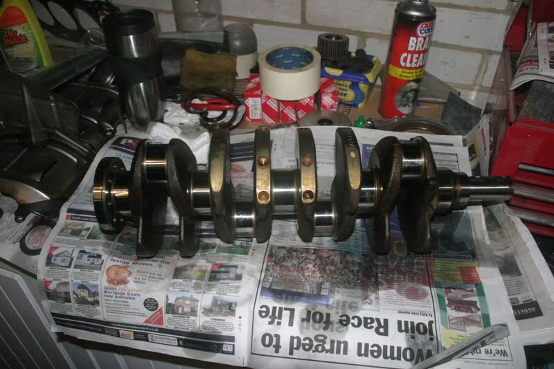 [/img]
And crank installed :D
Note socket on the end, it spins with a beautiful baby smooth action
[img]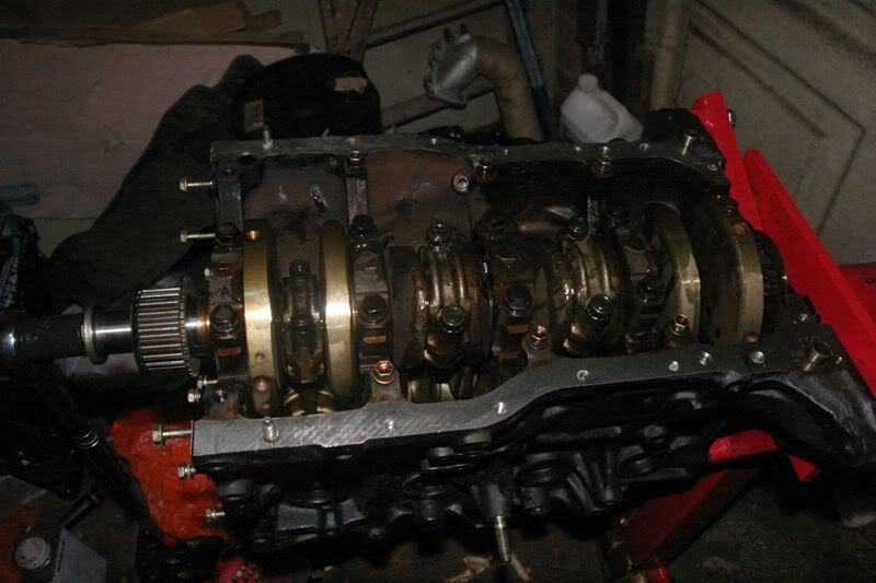 [/img]
Smoothness is certainly helped by lashings of semi synth gear oil used during assembley. You can see it running out of the bearings here
[img]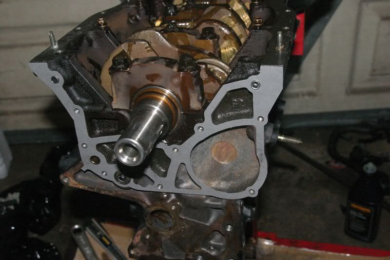 [/img]
Strainer and scraper plate re-installed
[img]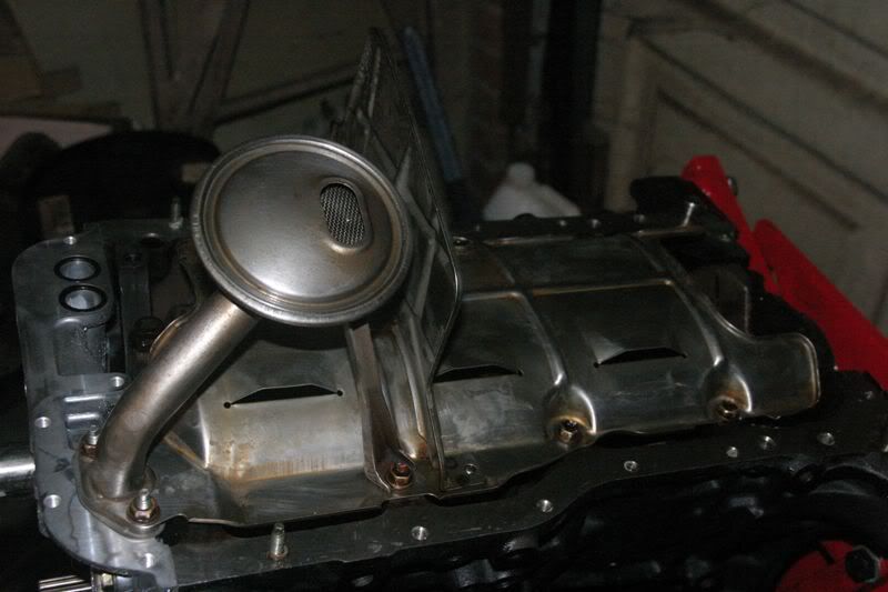 [/img]
Hmm, that bad feeling I had earlier isn't getting any better :(
[img]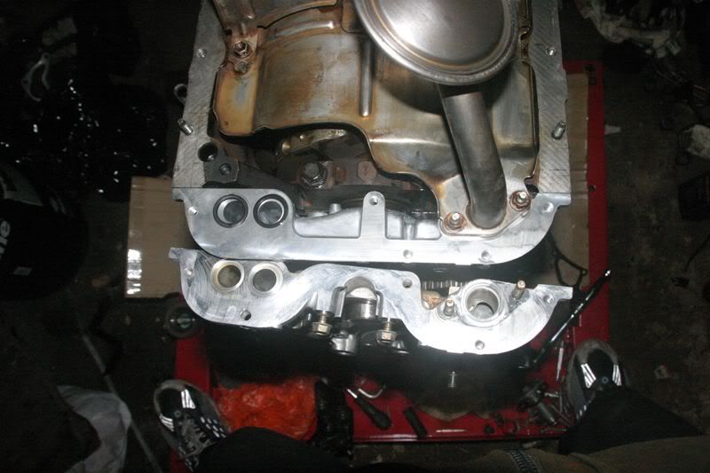 [/img]
DOH
I think that's going to leak. Looks like I'll have to pull the 205 sump and use that then. Still it'smostly bolted on now just to keep crud out of the engine
[img]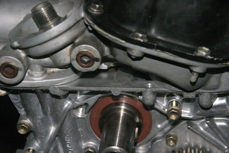 [/img]
Quick mockup to find out how many screws I have left :lol:
Water pump has to com off again as there's no housing behind it
[img]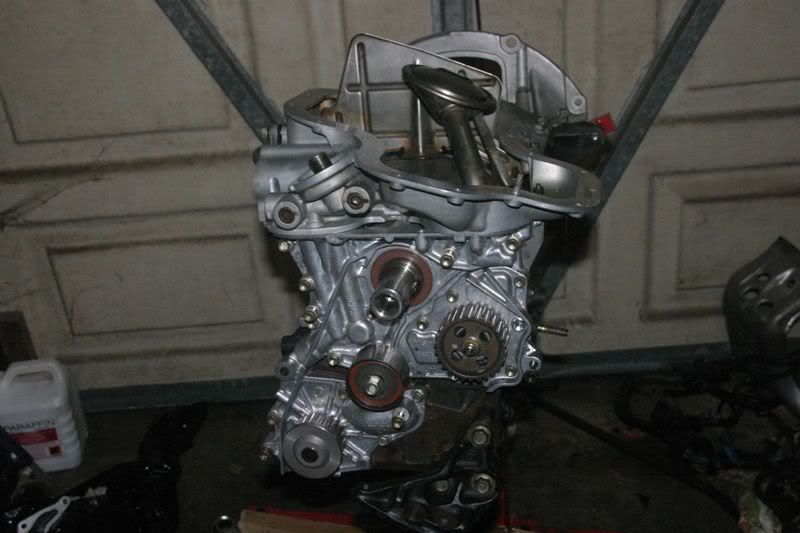 [/img]
You do not want to know how long it took to get the selaer off this. Suffice to say if I ever meet the person who ditched gaskets and specified sealant they will have a very very very very very bad day :mad:
[img]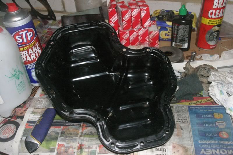 [/img]
Gratuitous pictures for Don
215 block doesn't use an adapter plate under the oil warm/cooler doughnut (mmmmm, doughnut) like the 205 one does
The centre face isn't very flat and probably needs machining to make a seal. A rubber washer might solve it though
[img]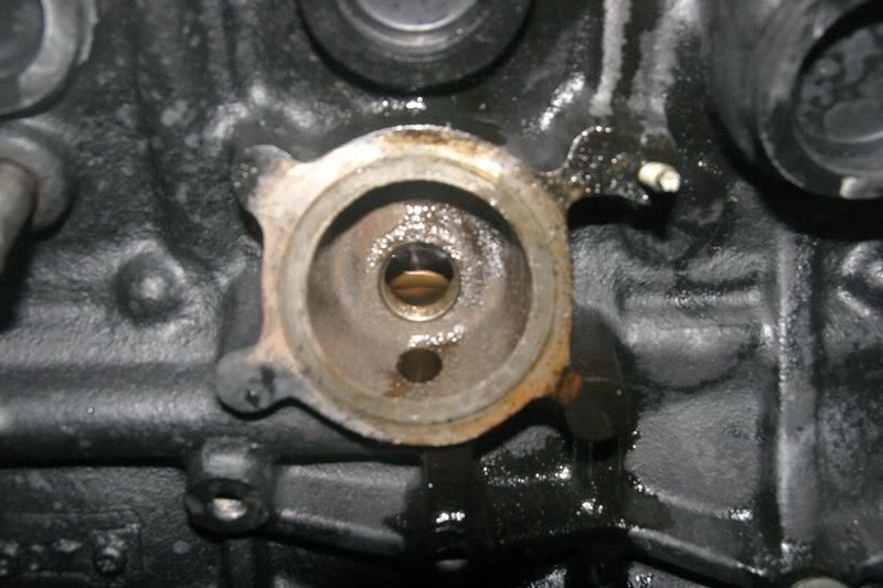 [/img]
The thread in the block is boggo standard 3/4 UNF oil filter thread which means standard oil filter fittings work fine
[img]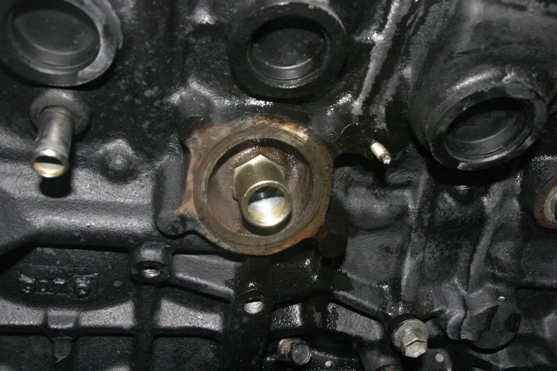 [/img]
Thermo takeoff plate fitted. you could replace this with a simple relocation housing with the ports blocked (or used if you want to take your oil cooler feed from here). Alternatively I'm sure the ST246 uses a blank cover in this location. Could be toyota to the rescue if you just want to blank it off
[img]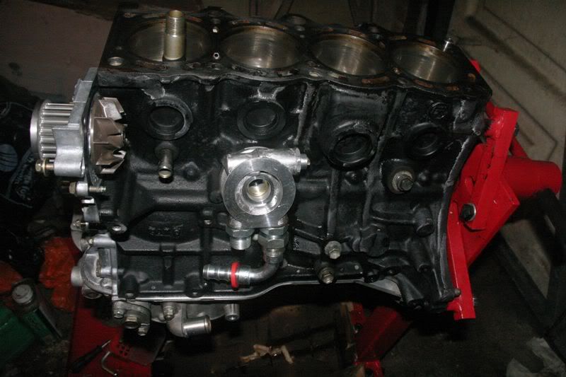 [/img]
Head has come back from the refurb. It's haf a 5 thou skim
Now I know it's been in the cleaner tank at the refinishers but this is why you absolutely must flush it out and highlights the power of my cheapskate pump solution :D
Water galleries had significant amounts of swarf
[img]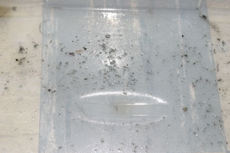 [/img]
[img]
[/img]
[img]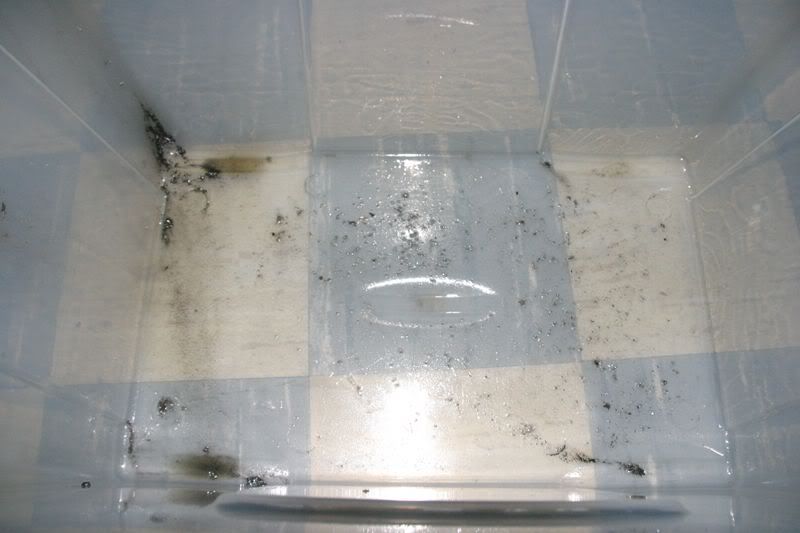 [/img]
Half way through shim resizing. I went with a grind on my oilstone followed by 1200 grit wet'n'dry with oil followed by a polish
[img]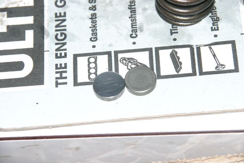 [/img]
Finally re-assembled head. After hours of tedious strip, rebuild, strip, adjust shim, strip measure strip adjust etc etc I ended up buying no shims and achieved the following clearances inlet from #1 to #8 (book tolerance 15 - 25) 21 21 20 20 20 21 19 19
exhaust #1 to #8 (book tolerance 28-38 )
33 33 33 32 33 33 33 33
[img]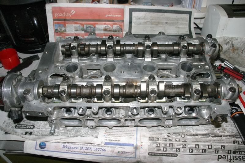 [/img]
Some 205 Vs 215 cylinder head comparisons
Top feed injector fitted to 215 head
[img]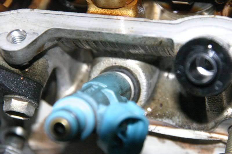 [/img]
It does not fit the 205 head :(
The entire 215 injector fits down the nozzle hole in the 205 head. It might be possible to fit with adapters if you really had to
[img]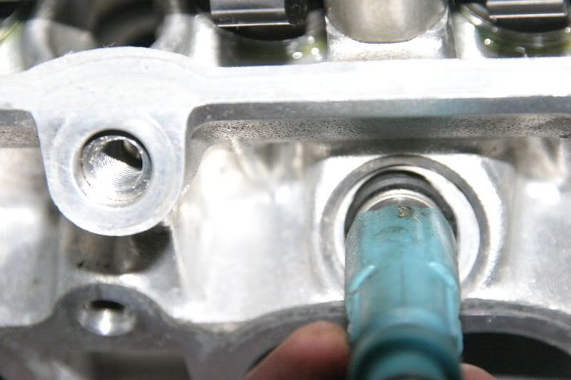 [/img]
Injector spacing is common between 205 and 215
[img]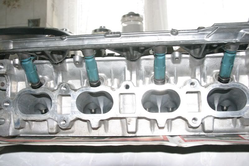 [/img]
Comparing 215 injector seats (first picture) with 205 injector seats You can see that on the 215 the injector seats are well clear of the inlet ports while on the 205 head the injector seats intrude into the port
The 215 head could be opened up significantly more because of this :twisted:
[img]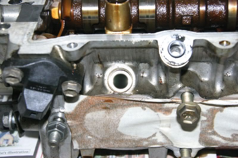 [/img]
[img]
[/img]
[img]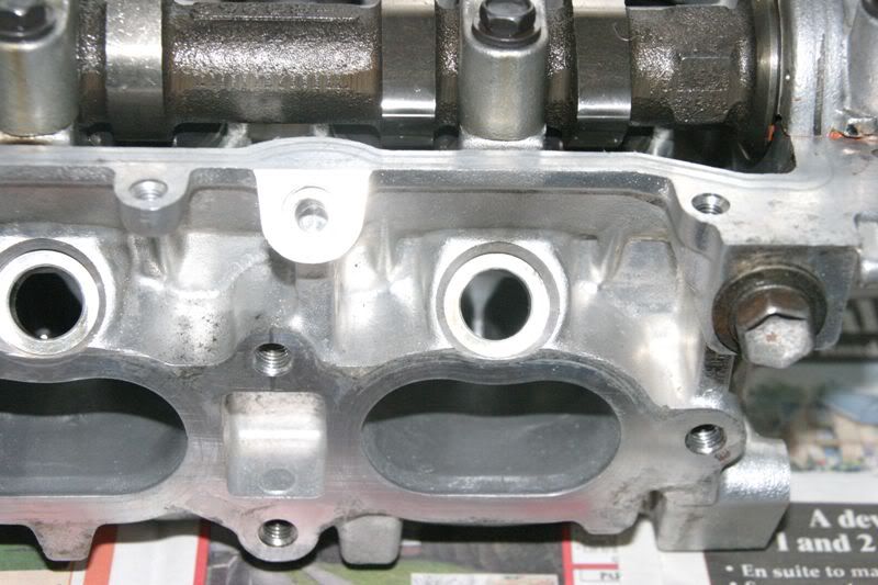 [/img]
st215 (first) compared to ST205. Notice that the 215 head does not have provision for the throttlebody support so a 205 rocker cover will not seal on a 215 head and conversely a 215 cover won't fit on a 205 head (also the 215 cover has no provision for the distributor so won't fit there either!)
I **think** that people using the wta intercooler are in trouble here. Possibly a 185 camcover will fit
[img]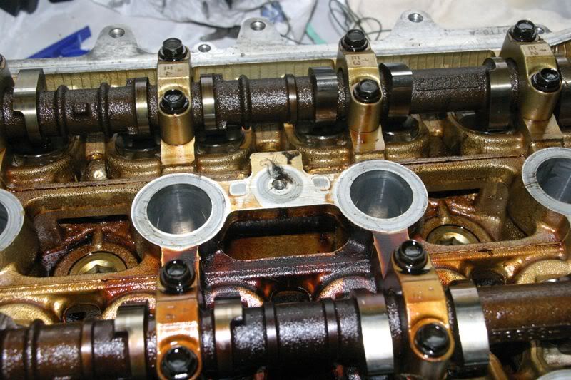 [/img]
[img]
[/img]
[img]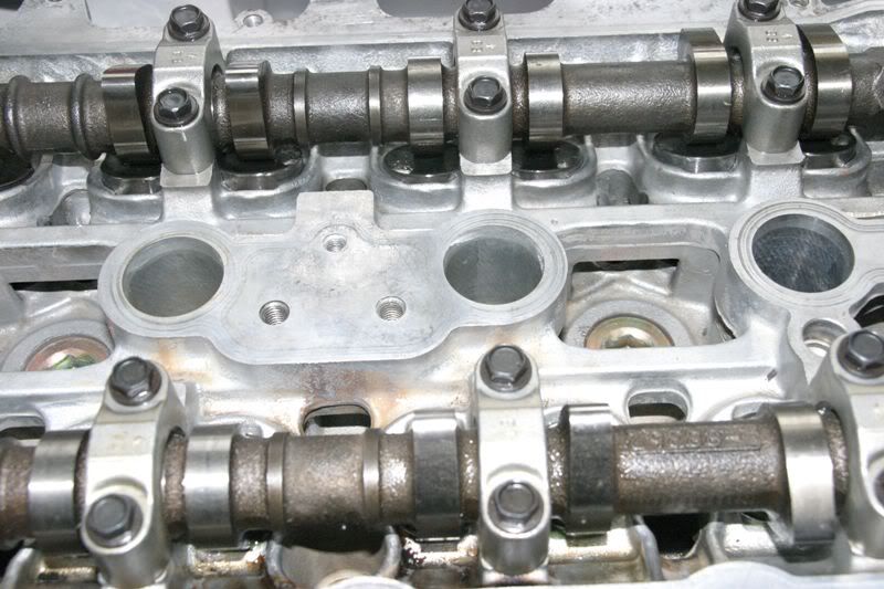 [/img]
There is some evidance of weight saving on the ST215 cams. Note that the non contacting ramp area has been narrowed (first picture) compared to the ST205 version
[img]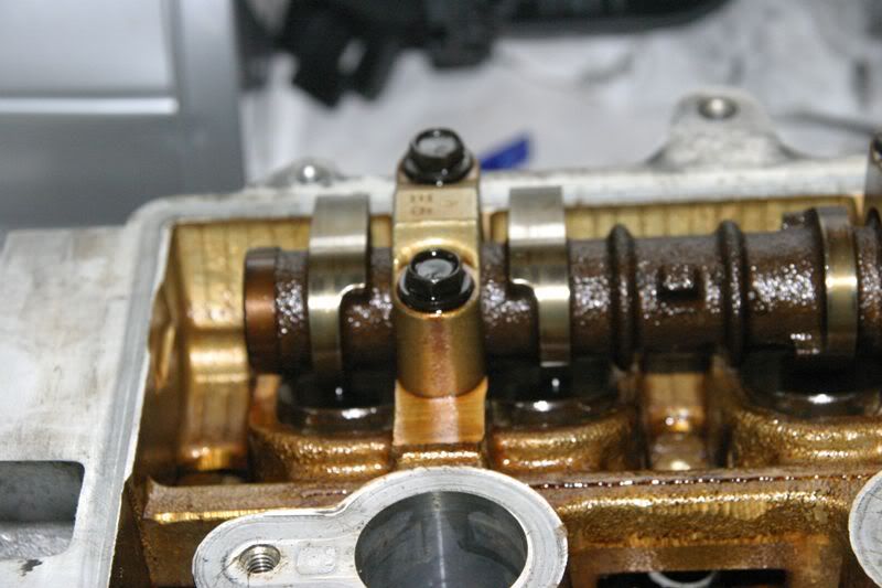 [/img]
[img]
[/img]
[img]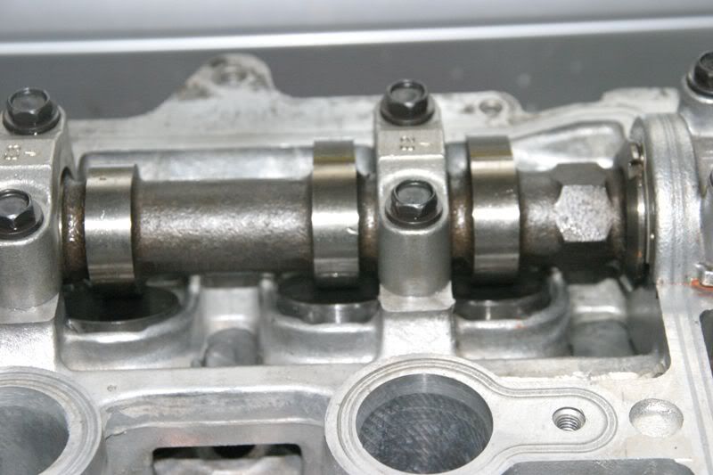 [/img]
ST205 head (first pic) has provision for a return from the standard catch can which is absent on the 215 head (second pic)
[img]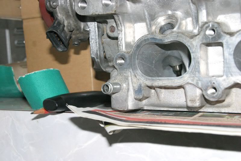 [/img]
[img]
[/img]
[img]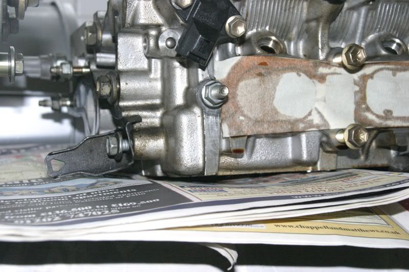 [/img]
The half moon blank used to remove the dizzy on the 215 and the hole in the head it fills up. I can't help but think that something used this head for them to include the provision for a dizzy. After all the head has been re-cast compared to the 205 and removing the dizzy would be easier than this apparent lash up
[img]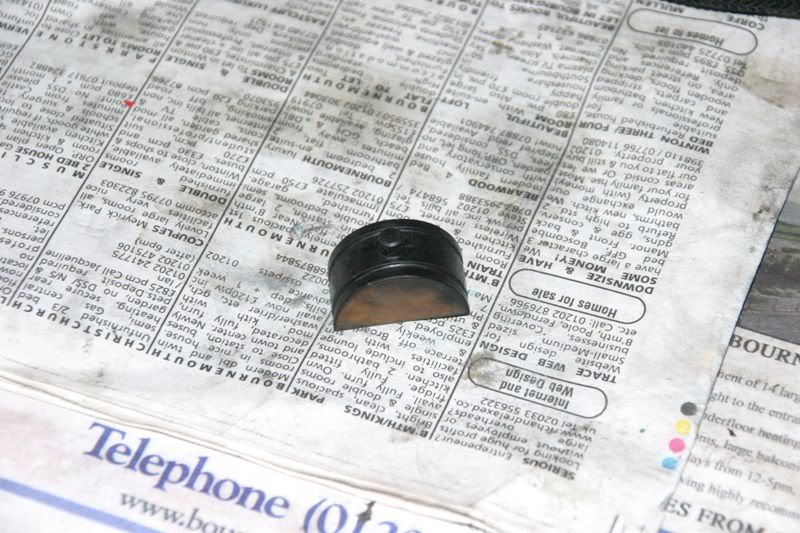 [/img]
[img]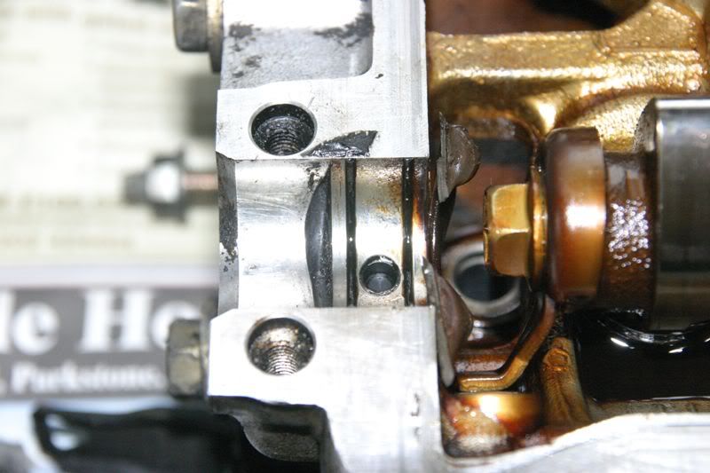 [/img]
Cam sensor trigger removed from cam. Looks like the cam has simply been line bored and threaded. The distributor location groove is absent also
[img]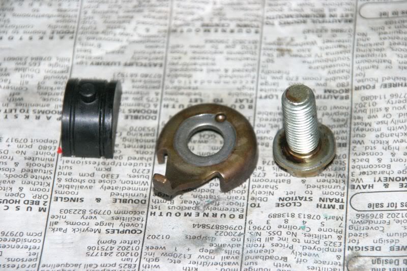 [/img]
[img]
[/img]
[img]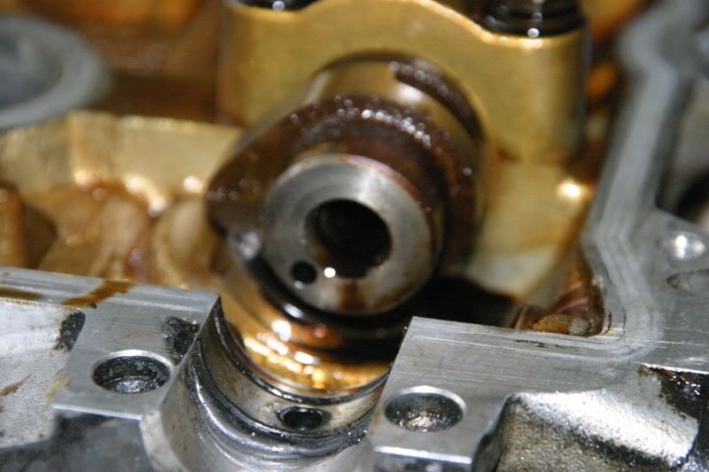 [/img]
The 215 head (first) looks much stronger compared to the 205 version. If you look at the bucket surround you can see that it's ~twice the thickness of the the 205 version. It's also apparent that all of the side to side "bracing" in the 215 head is much much thicker than the 205
I wonder if this stiffening is related in any way to block failure. It appears to me that they've tried to stiffen up the top of the bores with a stronger ladder brace in the head
[img]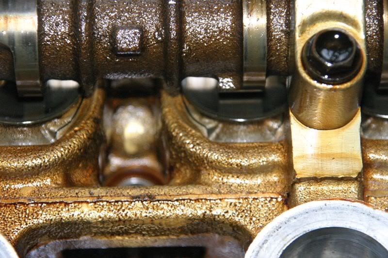 [/img]
[img]
[/img]
[img]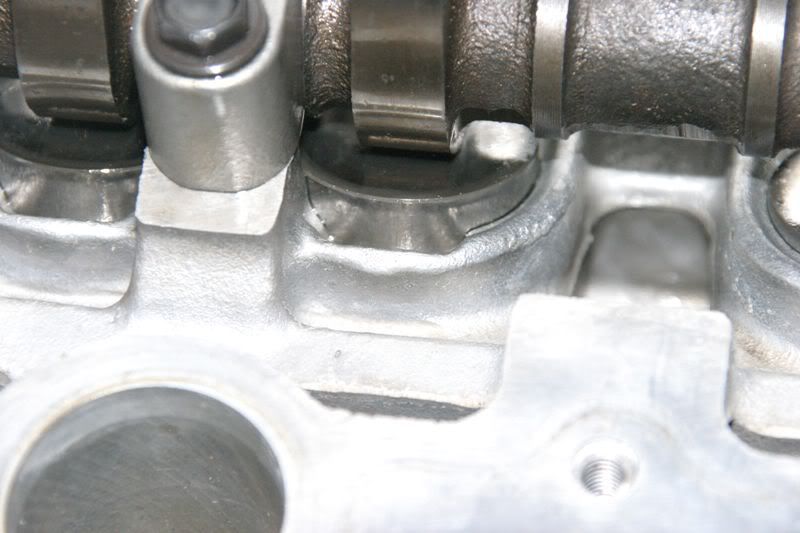 [/img]
ST215 (first) now lacks the camshaft witness marks to verify correct cambelt timing. Marks are clear on the second pic of the 205 (Note both pics are of the inlet cam and you can see the lobes are in approx the same position :lol: )
[img]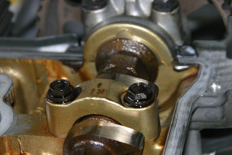 [/img]
[img]
[/img]
[img]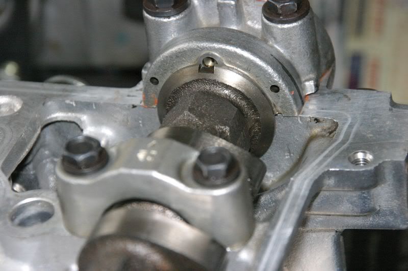 [/img]